Lubricating device of bearing

A technology of lubricating device and bearing, applied in the direction of engine lubrication, bearing components, shafts and bearings, etc., can solve the problems of reducing production efficiency, shortening the service life of shafts, increasing the expansion coefficient, etc., so as to improve production efficiency and prolong service life. , the effect of reducing friction

Inactive Publication Date: 2010-03-17
海门嘉濠建材贸易有限公司
View PDF1 Cites 10 Cited by
  • Summary
  • Abstract
  • Description
  • Claims
  • Application Information

AI Technical Summary

Problems solved by technology

[0002] The bearing is assembled on the shaft, and the bearing is concentric with the shaft and rotates around the concentric shaft. During use, the bearing will generate a certain amount of friction, which will cause wear to the bearing and affect the service life of the bearing. The traditional method is that during the assembly process, in the Apply lubricating grease on the bearing. The lubricating grease is a paste-like grease that lubricates the bearing. However, the heat dissipation effect of the lubricating grease is not ideal. With the use of the equipment, the lubricating grease will continue to volatilize and dry out. Re-apply grease on the mating surface, and apply grease again, only to disassemble the assembled bearing, which causes a lot of inconvenience and reduces production efficiency. At the same time, the bearing under high-speed rotation tends to heat up and heat up, which greatly increases friction. , there is a lubricating device for bearings, such as the patent No. 200820037152.9, an oil inlet throttle valve is set at the oil inlet of the lubricating chamber to control the amount of oil entering the lubricating chamber, which is convenient for adjusting the oil inlet, but the oil entering cannot be circulated , the heat dissipation capacity is low, due to the high-speed rotation of the shaft, the bearing will heat up and become hot, and the expansion coefficient will increase, which will still shorten the service life of the shaft

Method used


Image

  • Lubricating device of bearing
  • Lubricating device of bearing

Examples


Embodiment Construction

[0008] The present invention will be further described in detail below in conjunction with the accompanying drawings and embodiments.

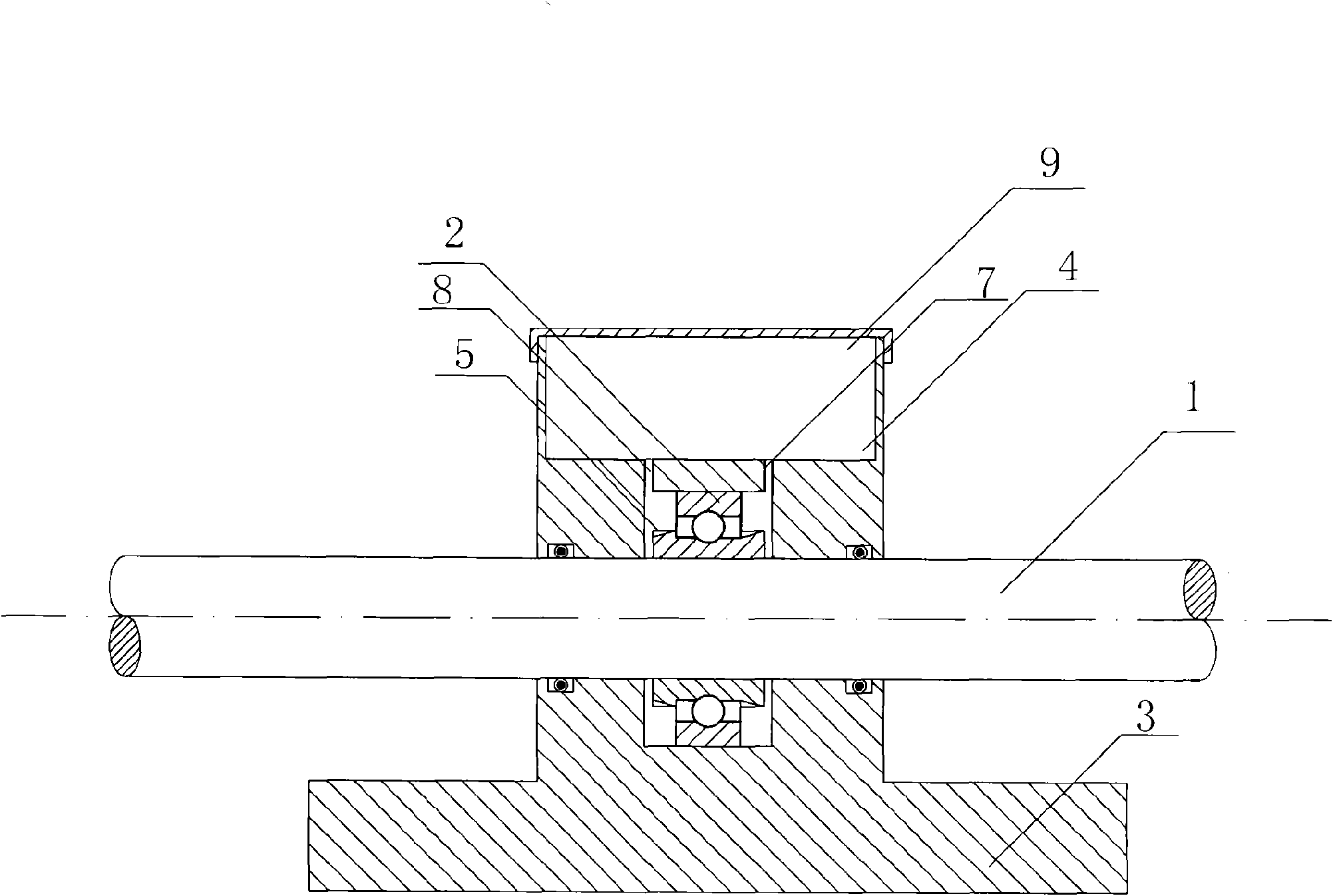
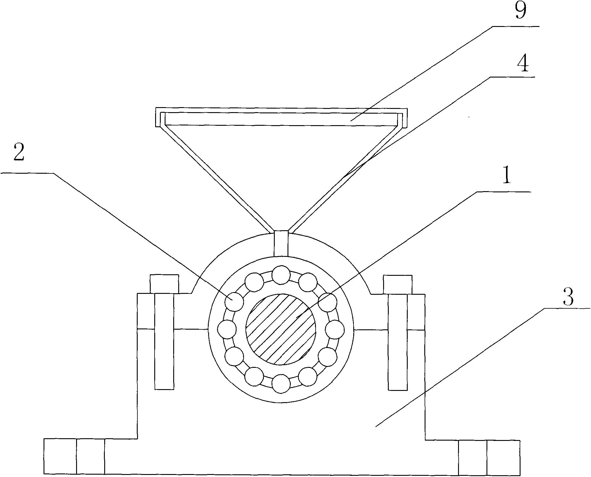
[0009] As shown in the figure: a bearing lubrication device, including a shaft 1, a bearing 2, a bearing seat 3 and an oil tank 4, the bearing 2 is arranged on the shaft 1, and an oil suction device 5 is arranged on at least one side of the bearing 2 along the axial direction, The oil suction device 5 is a worm gear device 6, and the bearing housing 3 is provided with an oil inlet hole 7 and an oil outlet hole 8 on the side of the shaft 1 provided with the oil suction device 5 and the opposite side, respectively, and the oil inlet hole 7 and the oil outlet hole 8 They are respectively connected to the oil tank 4 through oil pipes, the shaft 1 is fixed on the bearing seat 3 through the bearing 2, and an oil tank cover 9 is arranged above the oil tank 4 .


PUM


Abstract

The invention discloses a lubricating device of a bearing which comprises an axle, a bearing, a bearing block and an oil tank, wherein the bearing is arranged on the axle; the lubricating device is characterized in that at least one side of the bearing is provided with an oil suction device along the axle direction; the bearing block is provided with an oil inlet and an oil outlet at one side of the axle provided with a worm gear and at the opposite side respectively; the oil inlet and the oil outlet are respectively connected with the oil tank by an oil pipe; the lubricating device has the advantages that lubricant can be continuously supplied and added again without dismantling an assembled bearing, thus being convenient, saving time, increasing production efficiency and guaranteeing thebearing to be fully lubricated; simultaneously by the rotation of the worm gear, oil can circulate in the whole device, enter the oil tank from an oil inlet pipe and return to the oil tank again froman oil outlet pipe; heat generated by the oil that the oil tank gives off is utilized for reducing high temperature caused by high-speed rotation of the axle, thus reducing friction and prolonging the service life of the axle; moreover the lubricating device has simple structure, convenient operation and is particularly applicable to devices with large bearings.

Description

technical field [0001] The invention relates to a lubricating device for a bearing. Background technique [0002] The bearing is assembled on the shaft, and the bearing is concentric with the shaft and rotates around the concentric shaft. During use, the bearing will generate a certain amount of friction, which will cause wear to the bearing and affect the service life of the bearing. The traditional method is that during the assembly process, in the Apply lubricating grease on the bearing. The lubricating grease is a paste-like grease that lubricates the bearing. However, the heat dissipation effect of the lubricating grease is not ideal. With the use of the equipment, the lubricating grease will continue to volatilize and dry out. Re-apply grease on the mating surface, and apply grease again, only to disassemble the assembled bearing, which causes a lot of inconvenience and reduces production efficiency. At the same time, the bearing under high-speed rotation tends to heat...

Claims


Application Information

Patent Timeline
Patent Type & Authority Applications(China)
IPC IPC(8): F16N7/14F16C33/66
Inventor 陈兆红
Owner 海门嘉濠建材贸易有限公司
Why Eureka
Try Eureka