
LCD panel

A liquid crystal display panel and substrate technology, which is applied in nonlinear optics, instruments, optics, etc., can solve the problems such as pressing and dislocation of flexible circuit boards 2, and achieve the effect of ensuring the accuracy of alignment

Inactive Publication Date: 2010-03-17
AU OPTRONICS (SUZHOU) CORP LTD +1
View PDF0 Cites 16 Cited by
  • Summary
  • Abstract
  • Description
  • Claims
  • Application Information

AI Technical Summary

Problems solved by technology

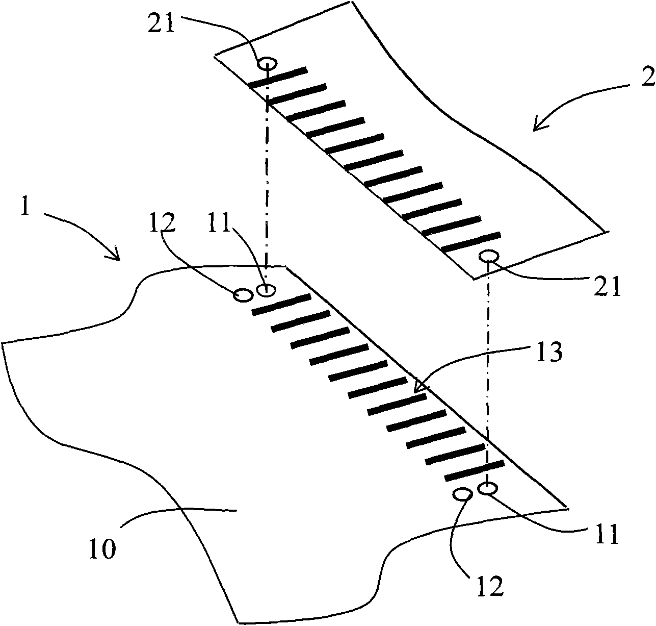
Due to the limitation of the wiring space on the substrate 10, the two alignment marks on the liquid crystal display panel 1 are often very close to each other, generally around 150 microns. Dislocation

Method used


Image

  • LCD panel
  • LCD panel
  • LCD panel

Examples


Embodiment Construction

[0016] In order to have a further understanding of the purpose, structure, features, and functions of the present invention, the following detailed descriptions are provided in conjunction with the embodiments.

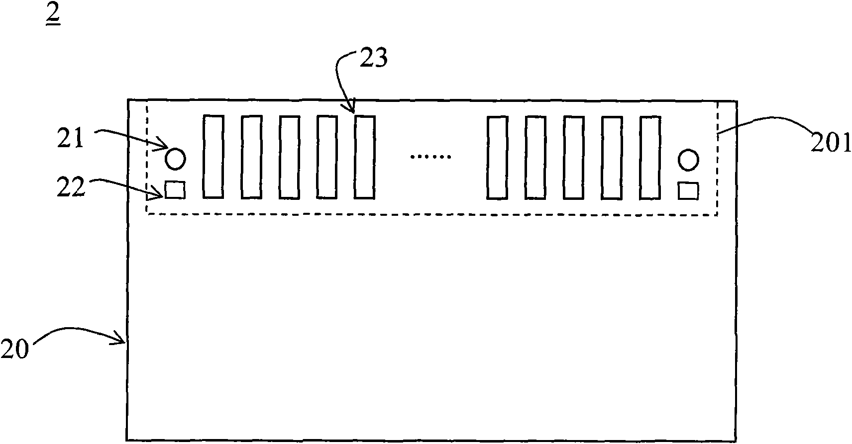
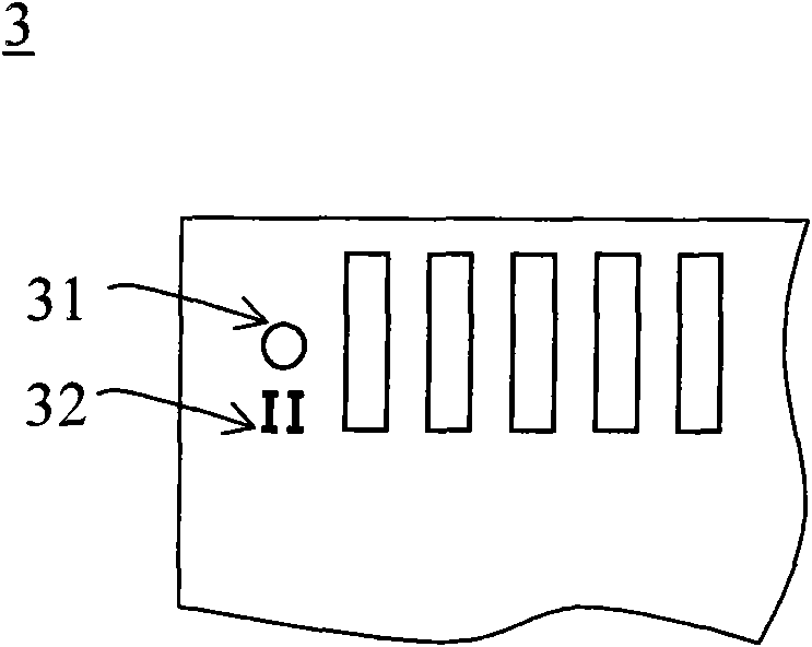
[0017] See figure 2 , figure 2 It is a schematic diagram of a liquid crystal display panel 2 according to an embodiment of the invention. The liquid crystal display panel 2 includes a substrate 20, pins 23, a first alignment mark 21 and a second alignment mark 22. The pins 23, the first alignment mark 21 and the second alignment mark 22 are provided on the substrate 20. The alignment mark 21 is used for pressing and alignment of the pins 23, and the shape of the first alignment mark 21 and the second alignment mark 22 are different. In one embodiment, the function of the second alignment mark 22 is different from that of the first alignment mark 21, for example, the second alignment mark 22 is used for alignment in the previous process. Such as figure 2 As shown, the...


PUM

PropertyMeasurementUnit
diameteraaaaaaaaaa

Abstract

The invention relates to an LCD panel, comprising a substrate, a pin, a first register mark and a second register mark, wherein the pin, the first register mark and the second register mark are arranged on the substrate, the first register mark is used for contraposition of the pin in a pressing manner, and the first register mark and the second register mark are in different shapes. The LCD panelcan ensure that an imaging element of a pressing machine does not mistake the register mark during the process that a flexible printed circutit is pressed on the LCD panel so as to more effectively ensure contraposition accuracy.

Description

Technical field [0001] The present invention relates to a liquid crystal display panel, in particular to a liquid crystal display panel with two alignment marks of different shapes. Background technique [0002] In the liquid crystal display module manufacturing process, the liquid crystal display panel and the driving circuit board are often connected through a flexible circuit board (FPC). At present, the pressing of flexible circuit boards uses the imaging elements (such as CCD) of the pressing machine to respectively grab the alignment marks on the flexible circuit board and the alignment marks on the LCD panel, and then automatically calculate the two through the program Then move the mechanism to the correct position, and press the flexible circuit board on the LCD panel. Therefore, the correctness of the pressing position of the flexible circuit board depends on the accuracy of the imaging element grasping the alignment marks on the liquid crystal display panel and the al...

Claims


Application Information

Patent Timeline
Patent Type & Authority Applications(China)
IPC IPC(8): G02F1/13
Inventor 杨成玮张爱云
Owner AU OPTRONICS (SUZHOU) CORP LTD
Learn More