Power control unit and on/off method

A technology for power control device and switch machine, which is applied to electronic switches, measurement devices, data processing power supplies, etc., can solve problems such as the inability to meet the power management requirements of embedded controllers, and achieves low cost, simple and easy-to-use circuits, and reliability. high effect

Inactive Publication Date: 2010-03-17
广州市能智威电子有限公司
View PDF0 Cites 24 Cited by
  • Summary
  • Abstract
  • Description
  • Claims
  • Application Information

AI Technical Summary

Problems solved by technology

[0004] The problem to be solved by the present invention is to provide a power control device and a switching method to overcome the defect that the power management chip of the communication terminal product in the prior art cannot meet the power management requirements of the embedded controller

Method used


Image

  • Power control unit and on/off method
  • Power control unit and on/off method
  • Power control unit and on/off method

Examples


Embodiment Construction

[0023] The specific implementation manners of the present invention will be further described in detail below in conjunction with the accompanying drawings and embodiments. The following examples are used to illustrate the present invention, but are not intended to limit the scope of the present invention.

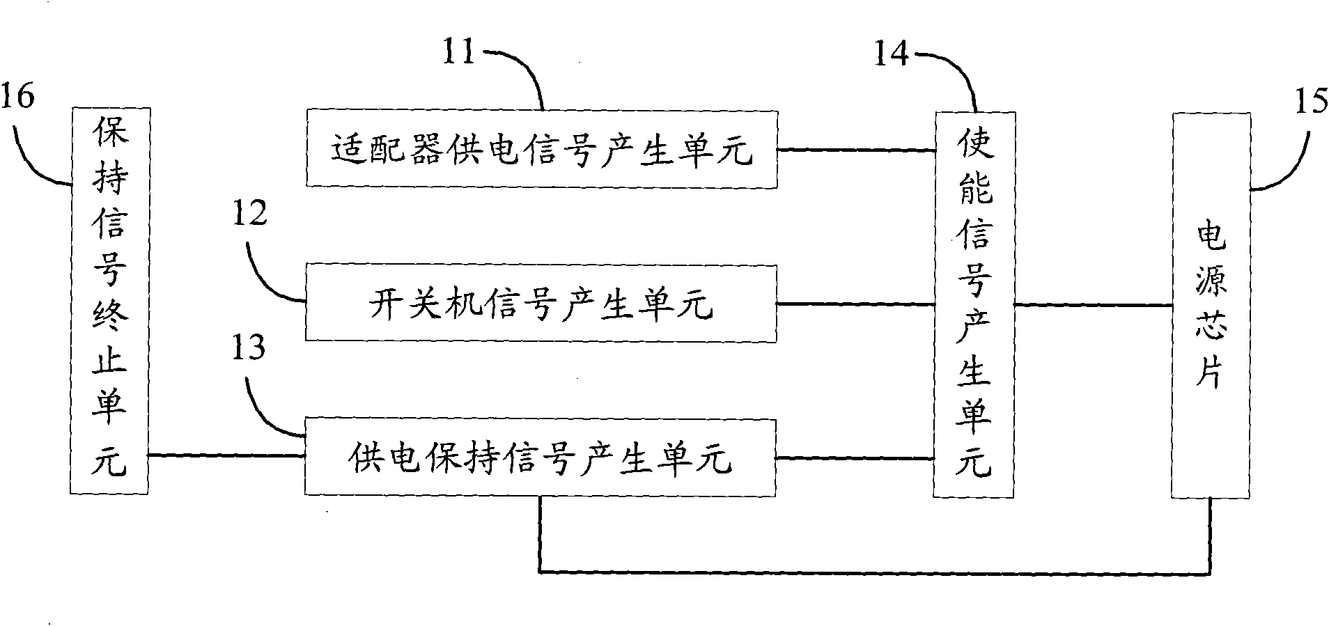
[0024] The present invention mainly realizes the power-on and power-off of the system through the control of the power chip; for the present invention, there are two events that trigger the power supply chip: 1. Adapter power supply; 2. Press the switch key when the battery power supply. These two actions can trigger the power supply of the power chip, so as to realize the power-on of the power system.

[0025] The structure of a power control device according to an embodiment of the present invention is as follows: figure 1 As shown, the device includes an adapter power supply signal generation unit 11 , a switch signal generation unit 12 , a power supply maintenance sig...


PUM


Abstract

The invention discloses a power control unit comprising an adapter power supply signal generating unit, an on/off signal generating unit, a power supply holding signal generating unit, an enable signal generating unit and a holding signal terminating unit. The adapter power supply signal generating unit is used for generating adapter power supply signals according to the output voltage of the adapter. The on/off signal generating unit is used for generating the on/off signals when cells supply power. The power supply holding signal generating unit is used for generating power supply holding signals when the cells supply power. The enable signal generating unit is used for generating enable signals according to the adapter power supply signals, on/off signals or power supply holding signalsand for controlling power on, power supply and power down of a power chip. The holding signal terminating unit is used for terminating generation of the power supply holding signals when the cells supply power. The invention also discloses an on method and an off method. The power control unit of the invention can provide stable supply voltage to embedded systems and realizes more complicated on/off power control flows of the terminal products. The power control unit realizes power on, power supply and power down processes of the system through the control of the circuit and the circuit is simple, easy to use, low in cost and high in reliability.

Description

technical field [0001] The present invention relates to the technical field of power management, in particular to a power control device and a switching method. Background technique [0002] With the development of communication electronic technology, there are more and more electronic products with more and more functions; electronic communication products with single function can no longer meet the needs of the market; communication tools with single voice function will gradually be replaced by multi-functional Replaced by electronic products; multifunctional electronic products integrate voice and high-speed data services; for electronic products, especially for electronic products with rich functions, the design of power supply is particularly important; with 3G (3rd Generation , the third generation digital communication) era, there will be more and more wireless access terminal products that integrate high-speed data services. For these multi-functional electronic prod...

Claims


Application Information

Patent Timeline
Patent Type & Authority Applications(China)
IPC IPC(8): G06F1/26H03K3/02H03K17/60H04W88/02
CPCG06F1/26H03K17/22
Inventor 段顶柱刘团辉王蔚
Owner 广州市能智威电子有限公司
Why Eureka
Try Eureka