Multi-display method and multi-display device

A multi-screen display and display unit technology, applied to static indicators, cathode ray tube indicators, instruments, etc., can solve the problems of cumbersome, time-consuming, and large processing capacity, and achieve the effect of improving efficiency and reducing processing capacity

Inactive Publication Date: 2010-03-17
GUANGDONG VTRON TECH CO LTD
View PDF0 Cites 18 Cited by
  • Summary
  • Abstract
  • Description
  • Claims
  • Application Information

AI Technical Summary

Problems solved by technology

In this prior art solution, all calculation processes for calculating the relevant parameters of each single board are carried out on the main control board. Control and management bring a huge burden and low efficiency, especially in the case of a large number of single boards, the processing volume is huge, the resulting time-consuming and burden is more obvious, and even affect the display on the splicing wall fluency of content

Method used


Image

  • Multi-display method and multi-display device
  • Multi-display method and multi-display device
  • Multi-display method and multi-display device

Examples


Embodiment 1

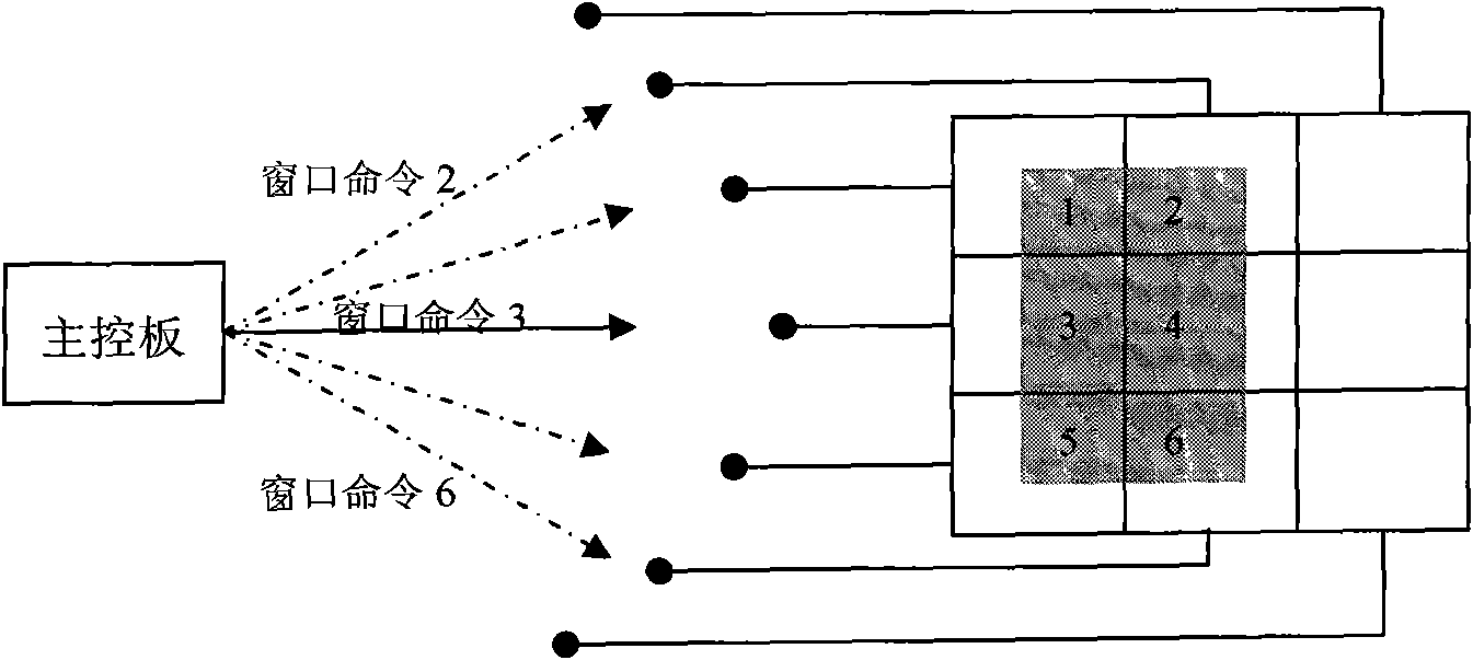
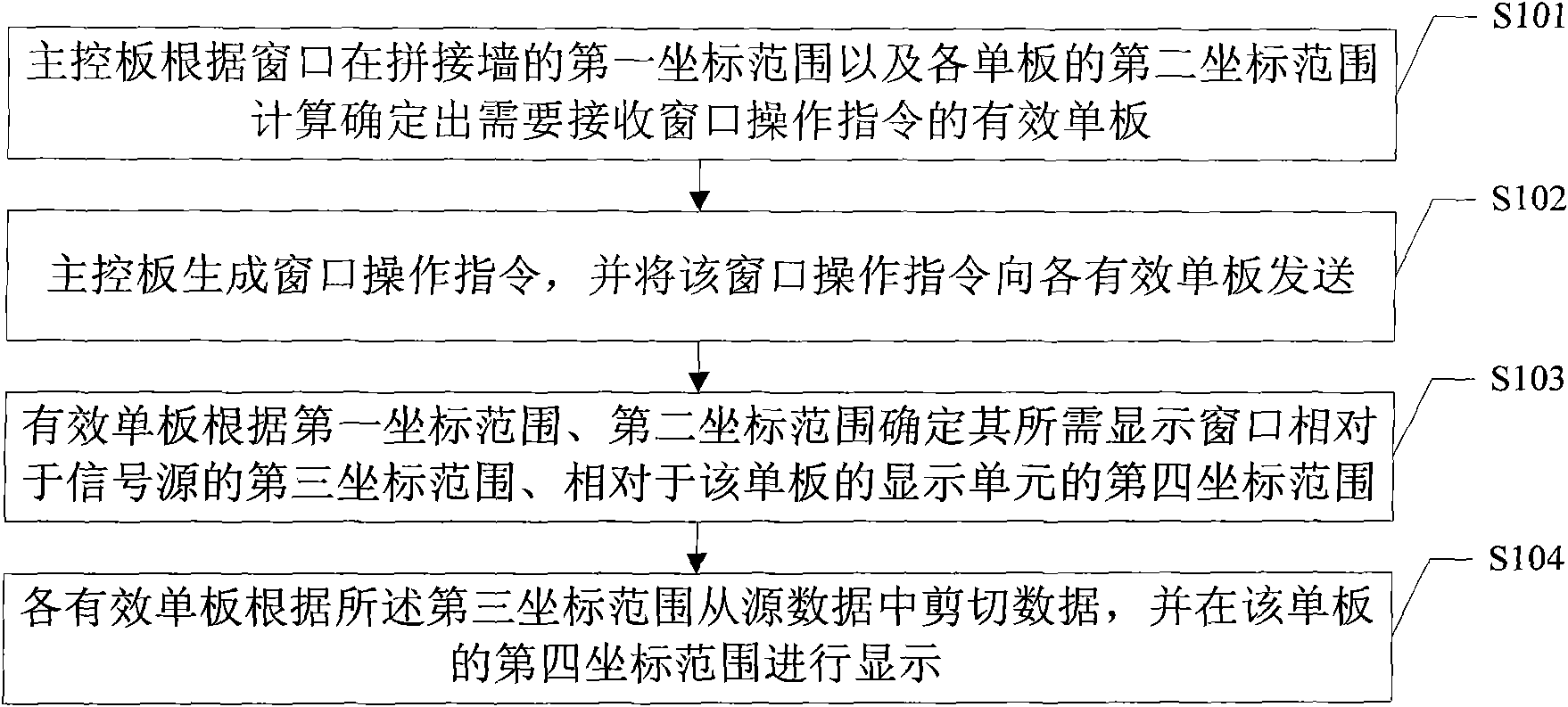
[0027] see image 3 As shown, it is a schematic flow chart of Embodiment 1 of the multi-screen display method of the present invention. In this embodiment, when the main control board sends a window operation command to a single board, it only performs multicast transmission to the single board that needs to be processed. , as shown in the figure, the multi-screen display method in this embodiment includes steps:

[0028] Step S101: According to the first coordinate range of the window on the splicing wall and the second coordinate range of the display unit corresponding to each veneer on the splicing wall, the main control board calculates the effective veneer that overlaps with the window. The single board is the single board that needs to receive the window operation instruction, enter step S102;

[0029] Step S102: The main control board generates a window operation instruction, and multicasts the window operation instruction to each of the above-mentioned effective singl...

Embodiment 2

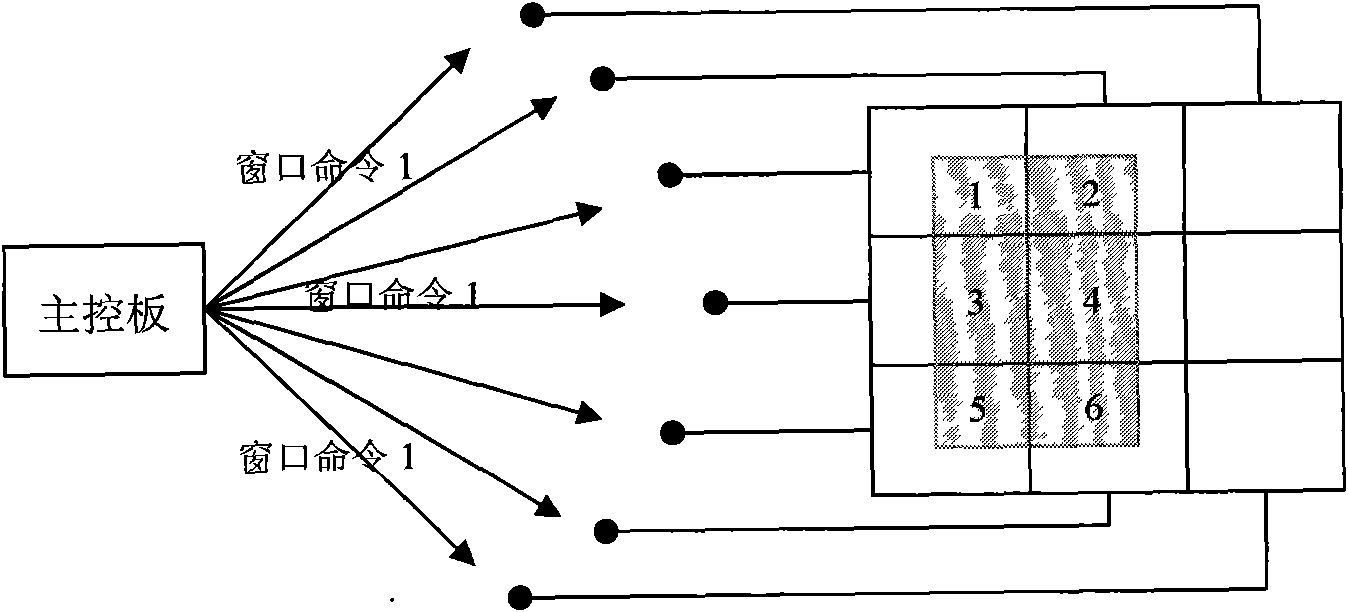
[0036] see Figure 4 As shown, it is a schematic flow chart of Embodiment 2 of the multi-screen display method of the present invention. The main difference between this embodiment and the above-mentioned Embodiment 1 is that in the solution of this embodiment, the main control board broadcasts to the All the boards send the window operation command, and each board judges whether it needs to receive the window operation command.

[0037] In the scheme of the first embodiment above, after the main control board calculates and determines the effective boards that need to receive window operation instructions, it only sends the window operation instructions to these effective boards for multicast transmission, which means that the main control board needs to have The window operation command is sent selectively, which brings inconvenience in processing.

[0038] like Figure 4 As shown, in the multi-screen display method of this embodiment, steps are included:

[0039] Step S2...


PUM


Abstract

The invention relates to a multi-display method and multi-display device. A master control board figures out the effective single board of overlaps with required display window, each single board figures out a third coordinate range of self required display window corresponding to a signal source and a fourth coordinate range of a corresponding display unit corresponding to the single board self according to a first coordinate range of window on a splicing wall and a second coordinate range of corresponding display unit of the single board self on the splicing wall, data is cut from the signalsource according to the third coordinate range, and the data is displayed on corresponding display unit according to the fourth coordinate range; namely the processing process executed by the mastercontrol board originally is completed by each single board by share, thus greatly reducing process load of the master control board, and each single board can process window display part required display processing, the process load is not high, thus the time for the whole processing and display is not too long and efficiency of processing and display is improved.

Description

technical field [0001] The invention relates to the technical field of splicing display, in particular to a multi-screen display method and a multi-screen display device. Background technique [0002] see figure 1 As shown, it is a schematic diagram of a multi-screen splicing solution in the prior art, which includes a main control board and a plurality of signal processing boards (hereinafter referred to as single boards), and each single board corresponds to the display unit in the splicing wall, and The main control board sends different window operation instructions to each board one by one for multi-screen splicing display processing. In the case of multi-screen display, the main control board calculates the relevant parameters of the windows that need to be processed by each board, for example Corresponding to the coordinate range of the display source, the coordinate range that needs to be on the display unit corresponding to the board, etc., and then generate differ...

Claims


Application Information

Patent Timeline
Patent Type & Authority Applications(China)
IPC IPC(8): G09G5/14G09G5/38
Inventor 吴鹏黄晓东
Owner GUANGDONG VTRON TECH CO LTD
Why Eureka
Try Eureka