Cascode circuit

一种放大器电路、阴地的技术,应用在放大器、射频放大器、放大器类型等方向,能够解决不能稳定并正常地工作、不能获得充分的输出等问题

Inactive Publication Date: 2010-03-17
MITSUBISHI ELECTRIC CORP
View PDF1 Cites 12 Cited by
  • Summary
  • Abstract
  • Description
  • Claims
  • Application Information

AI Technical Summary

Problems solved by technology

[0022] In the case where the cascode circuit has reflection gain, unnecessary oscillation occurs, and when the cascode circuit is applied to, for example, an amplifier, there is a problem that it may not work stably and normally.
[0023] In addition, when this cascode circuit is applied to, for example, an oscillator, there is a problem that a sufficient output cannot be obtained.

Method used


Image

  • Cascode circuit
  • Cascode circuit
  • Cascode circuit

Examples


Embodiment approach 1

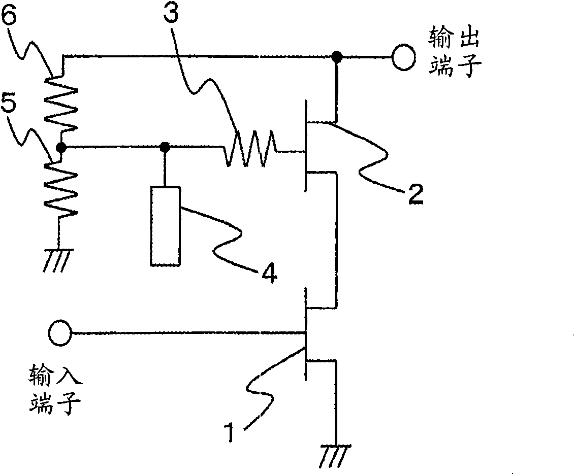
[0067] figure 1 It is a circuit diagram showing a cascode amplifier circuit according to Embodiment 1 of the present invention. In addition, this cascode circuit is configured so that MAG is optimized at 76 GHz (predetermined frequency).

[0068] exist figure 1 In , the drain of HEMT1 (first transistor) whose source is grounded is connected to the source of HEMT2 (second transistor) whose gate is grounded. That is, HEMT1 and HEMT2 are connected cascade-cascade. In addition, an input terminal is connected to the gate of HEMT1, and an output terminal is connected to the drain of HEMT2.

[0069] Also, a reflection gain suppression resistor 3 (signal improvement circuit) for suppressing reflection gain is connected to the gate of HEMT2. Also, an open stub 4 (filter circuit) for short-circuiting a high-frequency signal around a predetermined frequency is connected to the side of the reflection gain suppression resistor 3 opposite to the HEMT 2 . Here, the length of the open ...

Embodiment approach 2

[0094] Image 6 It is a circuit diagram showing an amplifier according to Embodiment 2 of the present invention. Among them, this amplifier is configured to have the maximum gain at 76 GHz (predetermined frequency).

[0095] exist Image 6 , HEMT1 and HEMT2 are cascaded and cascaded. In addition, an input terminal is connected to the gate of HEMT1, and an output terminal is connected to the drain of HEMT2.

[0096] In addition, a reflection gain suppressing resistor 3 for suppressing the reflection gain is connected to the gate of the HEMT2. In addition, between the source of HEMT1 and the gate of HEMT2, and between the gate of HEMT2 and the drain of HEMT2, voltage dividing resistors 5 and 6 for setting the gate voltage of HEMT2 are connected.

[0097] Also, on the opposite side of reflection gain suppression resistor 3 from HEMT2, replace figure 1 The shown straight open stub 4 is connected by a fan-shaped radial stub 7 . Like the open-circuit stub 4 , the radial stub 7 ...

Embodiment approach 3

[0109] Figure 9 It is a circuit diagram showing an amplifier according to Embodiment 3 of the present invention. In addition, this amplifier is configured as a wideband amplifier that can be used in a wideband.

[0110] exist Figure 9 , HEMT1 and HEMT2 are connected cascaded and cascaded. In addition, an input terminal is connected to the gate of HEMT1, and an output terminal is connected to the drain of HEMT2.

[0111] In addition, a reflection gain suppressing resistor 3 for suppressing the reflection gain is connected to the gate of the HEMT2. Also, an open stub 4 for short-circuiting a high-frequency signal around a predetermined frequency is connected to the side of the reflection gain suppressing resistor 3 opposite to the HEMT 2 . Here, the length of the open stub 4 is set to be shorter than 1 / 4 wavelength (λ / 4) of a high-frequency signal of a predetermined frequency (for example, 76 GHz) to be used.

[0112] Also, between the source of HEMT1 and the gate of HEMT...


PUM


Abstract

A cascode circuit for a high-gain or high-output millimeter-wave device that operates with stability. The cascode circuit including two cascode-connected transistors includes: a first high electron mobility transistor (HEMT) including a source that is grounded; a second HEMT including a source connected to a drain of the first HEMT; a reflection gain restricting resistance connected to the gate ofthe second HEMT, for restricting reflection gain; and an open stub connected to a side of the reflection gain restricting resistance which is opposite the side connected to the second HEMT, for short-circuiting high-frequency signals at a predetermined frequency and nearby frequencies.

Description

technical field [0001] The present invention relates to a cascode circuit used in the millimeter wave band. Background technique [0002] In recent years, applications using radio waves in the millimeter wave band, such as WPAN (Wireless Personal Area Network) in the 60 GHz band and millimeter wave radar in the 76 GHz band, have been increasing. Along with this, millimeter wave devices are required to have high gain and high output. [0003] As a general method for increasing power gain, there is known a method of cascading transistors. The so-called grid-to-cathode connection is a method of connecting the gate-grounded transistor to the drain of the source-grounded transistor, and the circuit formed is called a grid-to-cathode amplifier circuit. [0004] Hereinafter, a general conventional cascode amplifier circuit will be described with reference to the drawings. [0005] Figure 24 It is a circuit diagram showing a conventional cascode amplifier circuit. [0006] exis...

Claims


Application Information

Patent Timeline
Patent Type & Authority Applications(China)
IPC IPC(8): H03F1/22H03F3/60
CPCH03F3/1935H03F1/226H03F2200/541H03F1/0261H03F2200/18H03F2200/27H03F2200/534H03F2200/451H03F1/22H03F3/60
Inventor 金谷康后藤清毅渡边伸介
Owner MITSUBISHI ELECTRIC CORP
Why Eureka
Try Eureka