Configurations and methods for carbon dioxide and hydrogen production from gasification streams

一种脱碳、尾气的技术,应用在化学仪器和方法、分离方法、硫化合物等方向,能够解决成问题等问题

Inactive Publication Date: 2010-03-17
FLUOR TECH CORP
View PDF10 Cites 15 Cited by
  • Summary
  • Abstract
  • Description
  • Claims
  • Application Information

AI Technical Summary

Problems solved by technology

Unfortunately, such a configuration also produces enriched CO 2 acid gas, which is problematic for downstream sulfur plants

Method used


Image

  • Configurations and methods for carbon dioxide and hydrogen production from gasification streams
  • Configurations and methods for carbon dioxide and hydrogen production from gasification streams
  • Configurations and methods for carbon dioxide and hydrogen production from gasification streams

Examples


Embodiment Construction

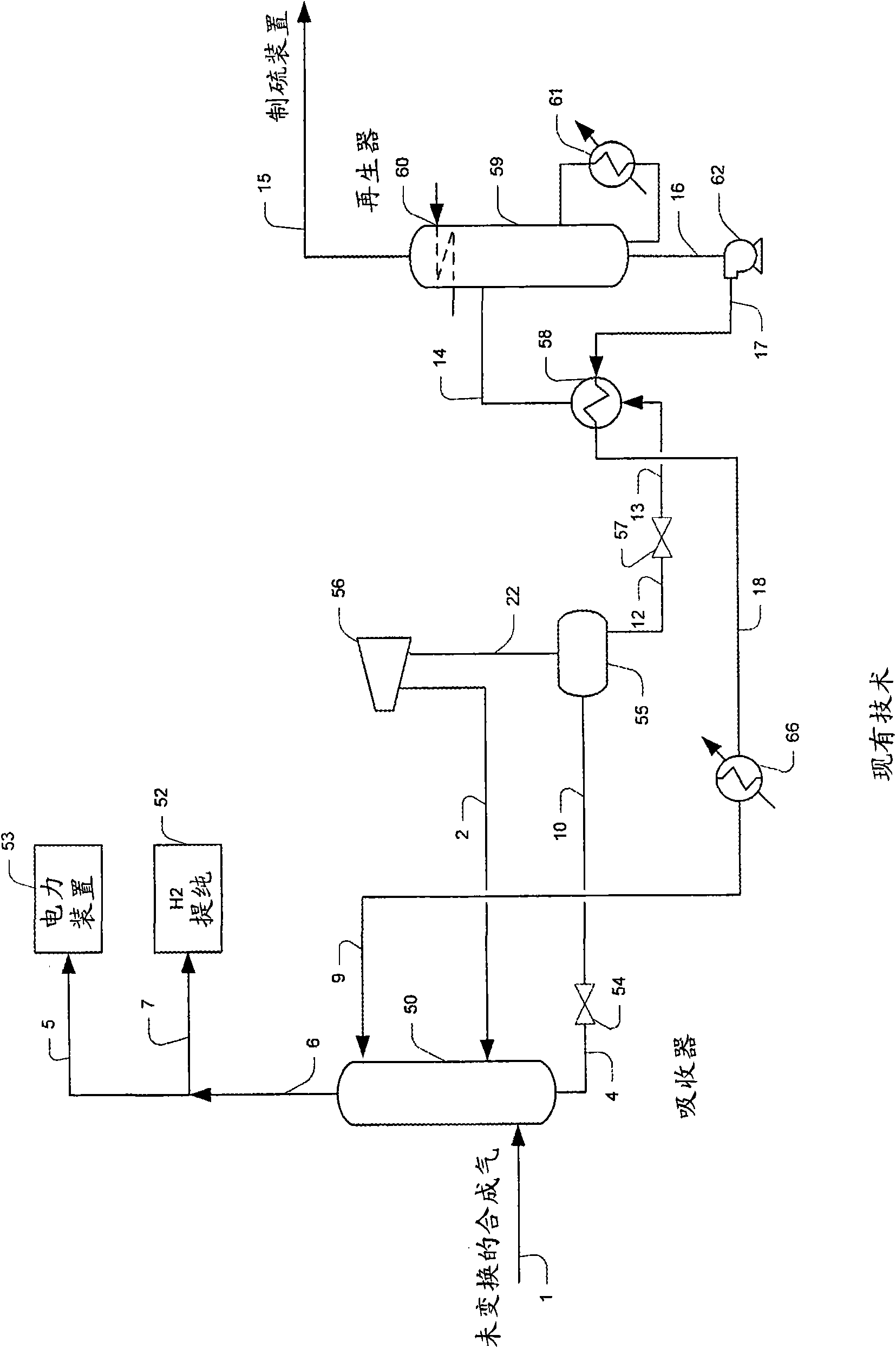
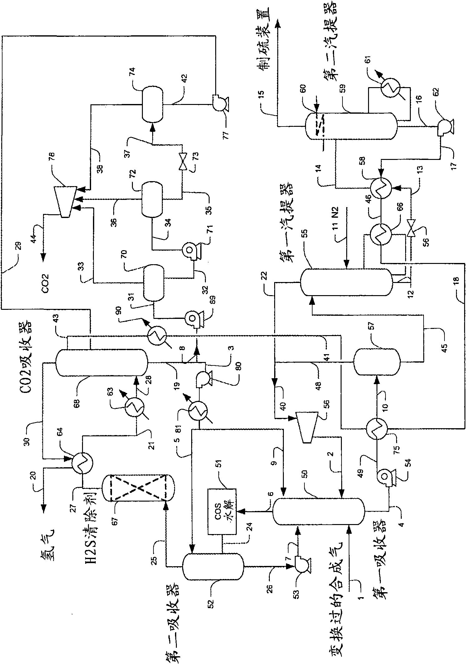
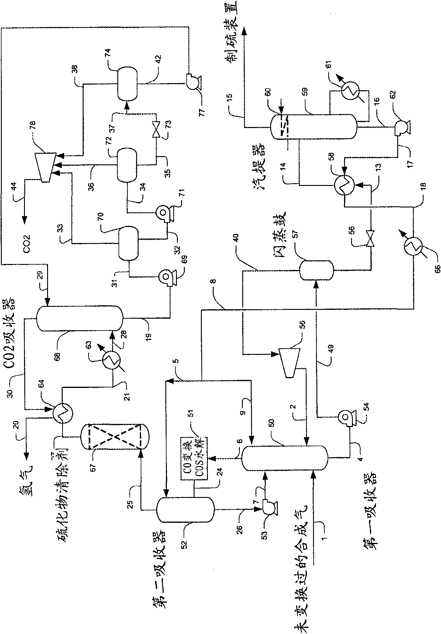
[0023] The present invention relates to methods for treating 2 , CO 2 , CO, H 2 Plant configuration and process for synthesis gas of S and COS, where hydrogen sulfide is removed in a first stage, and where carbon dioxide is removed in a second stage. Contemplated stages include absorbers in which a single solvent or separate and distinct solvents are used to absorb the respective acid gas components. Rich H 2 The S solvent is preferably regenerated using external heating in one or more stripper columns while the CO-enriched 2 The solvent is preferably regenerated by flashing the solvent to a lower pressure. In a particularly preferred arrangement, H 2 S absorbed in CO 2 Absorption takes place upstream.

[0024] In the case of low CO2 concentrations in the syngas (e.g., unshifted syngas), solvent recycle and use for H 2 S and CO 2 The solvent types of the absorber sections can be separate and different. On the other hand, in the case of higher CO2 concentrations in th...


PUM


Abstract

A syngas treatment plant is configured to remove sulfurous compounds and carbon dioxide from shifted or un-shifted syngas in a configuration having a decarbonization section and a desulfurization section. Most preferably, the solvent in the decarbonization section is regenerated and cooled by flashing, while the solvent is regenerated in the desulfurization section via stripping using external heat, and it is still further preferred that carbonylsulfide is removed in the desulfurization section via hydrolysis, and that the so produced hydrogen sulfide is removed in a downstream absorber.

Description

[0001] This application claims priority to the applicant's co-pending US Provisional Application 60 / 891133, filed February 22, 2007. technical field [0002] The technical field is the production of hydrogen and carbon dioxide from syngas streams, particularly arrangements and methods in which sulfur scavengers and solvents are used to reduce carbon and sulfur emissions. Background technique [0003] The gasification of coal, residual oil and other refinery waste is often combined with a combined cycle power plant (IGCC) to generate additional electricity. Syngas from gasification mainly includes H 2 , CO 2 , CO, H 2 S and COS are therefore often treated to remove sulfur where the syngas is used as fuel gas for power plants. While such IGCC plants are quite efficient at upgrading low-grade carbonaceous products to generate electricity, they often generate significant carbon and sulfur emissions, particularly from gas turbine exhaust (e.g., sulfur oxides, CO 2 Wait). [...

Claims


Application Information

Patent Timeline
Patent Type & Authority Applications(China)
IPC IPC(8): B01D53/62C01B32/50
CPCC01B2203/0475C01B2203/0485C01B17/0456C01B3/52B01D2257/304B01D2256/16B01D2257/504C01B17/164Y02C10/06Y02C10/04C01B2203/0415C01B17/04B01D53/1406C01B31/20C01B2203/86B01D53/1475B01D53/1462C01B32/50Y02C20/40Y02P30/00Y02P20/151
Inventor J·马克R·尼尔森
Owner FLUOR TECH CORP
Why Eureka
Try Eureka