This helps you quickly interpret patents by identifying the three key elements:
Problems solved by technology
Method used
Benefits of technology
Problems solved by technology
In this compressor, the refrigerant discharged from the compression mechanism tends to become high temperature, which may cause the compression mechanism to malfunction.
Method used
Image
Click on the blue label to locate the original text in one second.
Reading with bidirectional positioning of images and text.
Examples
no. 1 Embodiment approach
[0077] 1. The structure of the scroll compressor
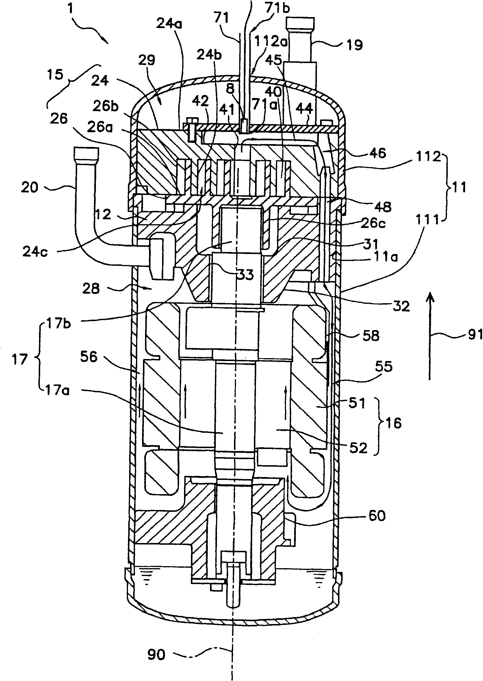
[0078] figure 1 It is a conceptual diagram of the scroll compressor 1 which concerns on 1st Embodiment of this invention. exist figure 1 The direction 91 is shown in , and hereinafter, the front end side of the arrow of the direction 91 is called "upper side", and the opposite side is called "lower side".
[0079] The scroll compressor 1 includes a casing 11 , a stationary member 12 , a compression mechanism 15 , a motor 16 , a crankshaft 17 , a suction pipe 19 , a discharge pipe 20 , and a bearing 60 .
[0080] The housing 11 has a cylinder 111 and a cover 112 extending in the direction 91 . The cover 112 covers the upper end of the cylinder 111 . A fixed member 12 , a compression mechanism 15 , an electric motor 16 , a crankshaft 17 , and a bearing 60 are housed in the housing 11 .
[0081] The motor 16 has a stator 51 and a rotor 52 . The stator 51 is annular and fixed to the inner wall 11 a of the housing 11 . The r...
no. 2 Embodiment approach
[0129] (Structure of the scroll compressor 201)
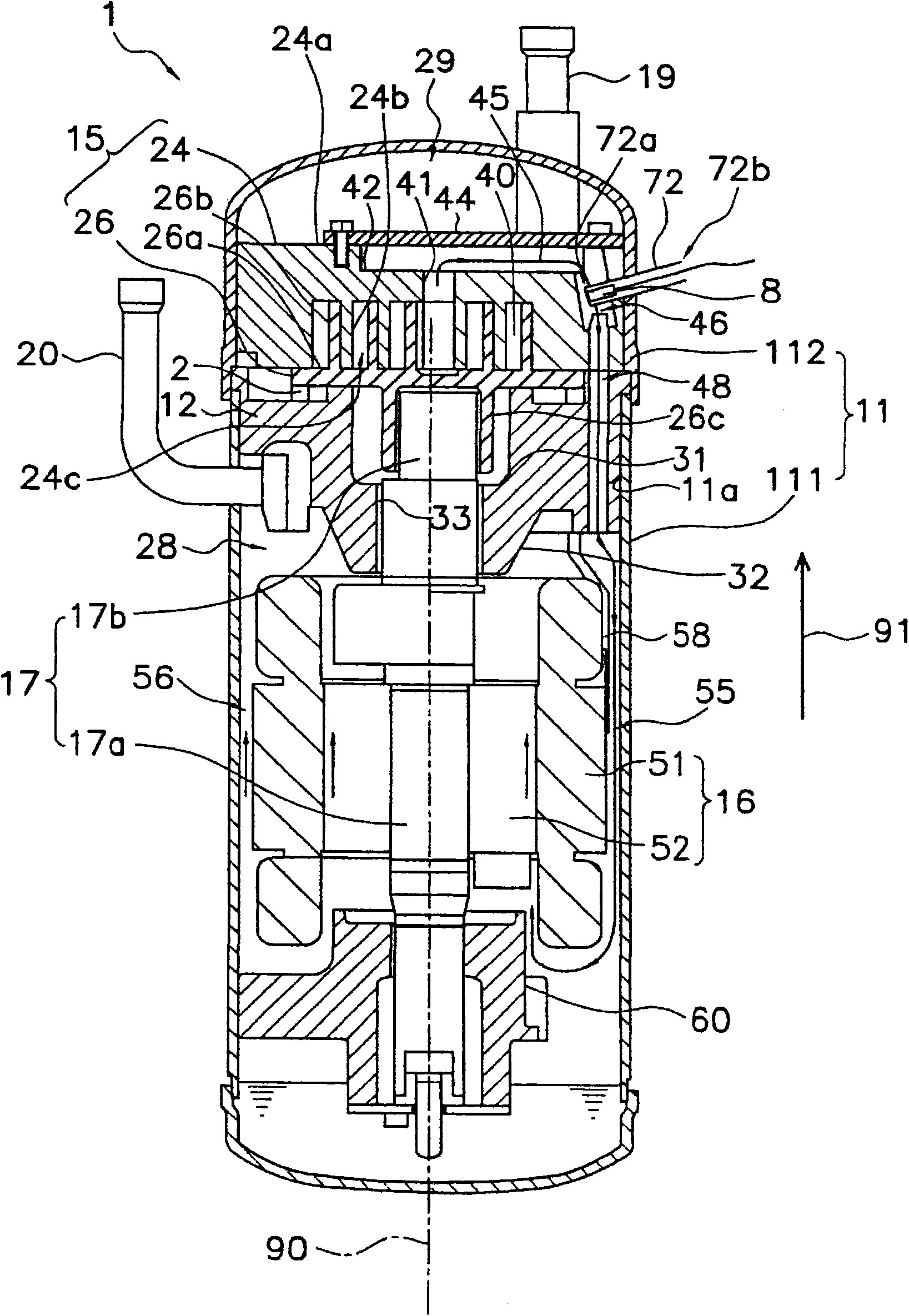
[0130] Figure 6 It is a conceptual diagram of the scroll compressor 201 which concerns on 2nd Embodiment of this invention. Figure 6 The illustrated scroll compressor 201 is constructed substantially the same as figure 1 The scroll compressor 1 shown in common, in Figure 6 in, with figure 1 The same notation as in figure 1 The components shown are the same components.
[0131] which is, Figure 6 The illustrated scroll compressor 201 includes a casing 11 , a stationary member 12 , a compression mechanism 15 , a motor 16 , a crankshaft 17 , a suction pipe 19 , a discharge pipe 20 , a bearing 60 , and a guide plate 58 .
[0132] exist Figure 6 In the fixed member 12 shown, the recessed part 31 and the hole 33 are comprised by the roller bearing which fits in the fixed member 12. As shown in FIG.
[0133] The motor 16 is arranged under the compression mechanism 15 and is a driving source of the compression mechanism 15...
PUM
Abstract
A scroll compressor in which measurement of the temperature of refrigerant flowing in a path is facilitated. The scroll compressor (1) has a housing (11), a compression mechanism (15), and a pipe (71). A space (45) functioning as the path for the refrigerant is provided inside the housing (11). The compression mechanism (15) compresses the refrigerant and discharges it to the space (45) from a discharge opening (41). The pipe (71) extends from the inside of the housing (11) to the outside and has one end (71a) and the other end (71b). The one end (71a) is located at a predetermined position inthe space (45), or more specifically, at a position near the discharge opening (41), and is closed. The other end (71b) is located outside the housing (11) and is open. A measurement device (8) is inserted into the pipe (71) from the other end (71b).
Description
technical field [0001] The present invention relates to a compressor, and in particular to measuring the temperature of a refrigerant. The invention also relates to a refrigeration unit using a compressor. Background technique [0002] The compressor includes a compression mechanism that compresses the refrigerant, and a housing that accommodates the compression mechanism. A passage through which refrigerant compressed in the compression mechanism flows is provided inside the casing. [0003] In particular, in refrigeration compressors, the circulating volume of refrigerant is small, and it is necessary to drive the compression mechanism at a high compression ratio. In this compressor, the refrigerant discharged from the compression mechanism tends to become high in temperature, which may cause failure of the compression mechanism. Thus, it is necessary to measure the temperature of the discharged refrigerant and then control the operation of the compressor. [0004] The...
Claims
Application Information
Patent Timeline
Application Date:The date an application was filed.
Publication Date:The date a patent or application was officially published.
First Publication Date:The earliest publication date of a patent with the same application number.
Issue Date:Publication date of the patent grant document.
PCT Entry Date:The Entry date of PCT National Phase.
Estimated Expiry Date:The statutory expiry date of a patent right according to the Patent Law, and it is the longest term of protection that the patent right can achieve without the termination of the patent right due to other reasons(Term extension factor has been taken into account ).
Invalid Date:Actual expiry date is based on effective date or publication date of legal transaction data of invalid patent.

