Isolated gate bipolar transistor driving circuit

A bipolar transistor, driving circuit technology, applied in electrical components, electronic switches, pulse technology and other directions, can solve the problems of accelerated loss, IGBT impact, IGBT electrical stress, etc., to reduce electrical stress, suppress the instantaneous turn-off Voltage dv/dt, effect of suppressing on-transient current

Active Publication Date: 2010-03-24
BYD CO LTD
View PDF0 Cites 10 Cited by
  • Summary
  • Abstract
  • Description
  • Claims
  • Application Information

AI Technical Summary

Problems solved by technology

[0002] The current insulated gate bipolar transistor (hereinafter referred to as IGBT) drive circuit generally uses a pulse width modulation (PWM) signal to control the on and off of the IGBT. This drive circuit is currently divided into three types: optocoupler transmission isolation Drive circuit, this drive circuit is suitable for small-capacity inverters; pulse transformer transmission isolation drive circuit, this drive circuit is suitable for large-capacity inverters, and is widely used in large-capacity electric vehicles; there is also a fiber optic Transmission isolation drive circuit, this drive circuit is better, but the cost is too high, not commonly used in practical applications
[0003] In the pulse transformer transmission isolation drive circuit, due to the relatively large transmitted voltage, the instantaneous current di / dt and the instantaneous voltage dv / dt when the IGBT is turned on each time will be very large, so that the electrical stress of the IGBT is also very large , will bring impact to IGBT and accelerate its loss

Method used


Image

  • Isolated gate bipolar transistor driving circuit
  • Isolated gate bipolar transistor driving circuit
  • Isolated gate bipolar transistor driving circuit

Examples


Embodiment Construction

[0015] The present invention will be further described below in conjunction with the accompanying drawings.

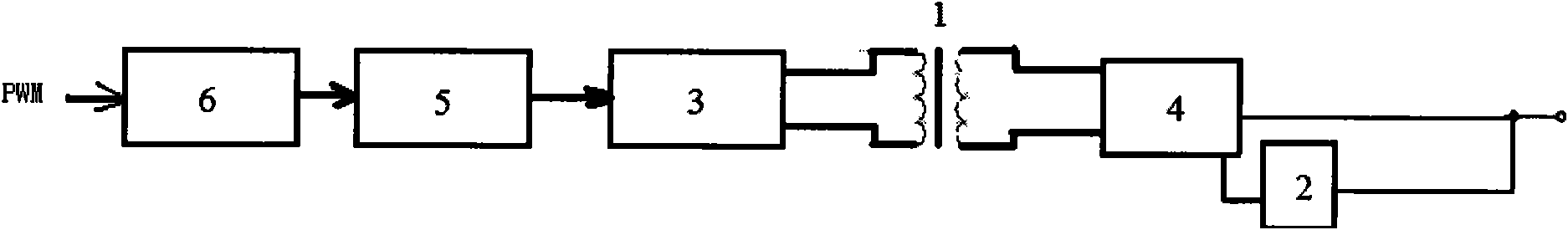
[0016] Such as figure 1 As shown, the present invention provides an IGBT drive circuit, the drive circuit includes: a transformer 1, the primary side of the transformer 1 is used to receive a PWM signal, wherein the drive circuit also includes a charging and discharging module 2, the secondary side of the transformer 1 The stage side is used to connect the gate of the insulated gate bipolar transistor, and is connected to the input terminal of the charging and discharging module 2, and the output terminal of the charging and discharging module 2 is used to be connected to the gate of the insulated gate bipolar transistor. The discharge module 2 is used to receive the PWM signal output by the secondary side of the transformer 1, and charge or discharge the IGBT according to the PWM signal so that the IGBT is turned on before are precharged and predischarged before shut...


PUM


Abstract

The invention discloses an isolated gate bipolar transistor driving circuit comprising a transformer (1), and a primary side of the transformer (1) is used for receiving pulse width modulation signals. The invention is characterized by also comprising a charge-discharge module (2), wherein, a secondary side of the transformer (1) is used for connecting a gate pole of an isolated gate bipolar transistor, and is connected with the input end of the charge-discharge module (2); the output end of the charge-discharge module (2) is used for connecting with the gate pole of the isolated gate bipolartransistor; the charge-discharge module (2) is used for receiving the pulse width modulation signals output by the secondary side of the transformer (1), and charges or discharges to the isolated gatebipolar transistor according to the pulse width modulation signals to lead the isolated gate bipolar transistor to be precharged before power on and to be predischarged before power off. The drivingcircuit can effectively inhabit power on of instantaneous current di / dt and power off of instantaneous voltage dv / dt so as to achieve the purpose of reducing the electric stress of the isolated gate bipolar transistor.

Description

technical field [0001] The invention relates to an insulated gate bipolar transistor (IGBT) drive circuit. Background technique [0002] The current insulated gate bipolar transistor (hereinafter referred to as IGBT) drive circuit generally uses a pulse width modulation (PWM) signal to control the on and off of the IGBT. This drive circuit is currently divided into three types: optocoupler transmission isolation Drive circuit, this drive circuit is suitable for small-capacity inverters; pulse transformer transmission isolation drive circuit, this drive circuit is suitable for large-capacity inverters, and is widely used in large-capacity electric vehicles; there is also a fiber optic Transmission isolation drive circuit, this kind of drive circuit is better, but the cost is too high, so it is not commonly used in practical applications. [0003] In the pulse transformer transmission isolation drive circuit, due to the relatively large transmitted voltage, the instantaneous ...

Claims


Application Information

Patent Timeline
Patent Type & Authority Applications(China)
IPC IPC(8): H03K17/567
Inventor 彭应葱张朕清
Owner BYD CO LTD
Why Eureka
Try Eureka