
Electroluminescent device having improved light output

A device and light-emitting layer technology, applied in the field of planar electroluminescent device structure, can solve the problems of reducing the output efficiency of electroluminescent devices, achieve the effect of improving light extraction efficiency and prolonging the use time

Active Publication Date: 2010-03-24
GLOBAL OLED TECH
View PDF45 Cites 45 Cited by
  • Summary
  • Abstract
  • Description
  • Claims
  • Application Information

AI Technical Summary

Problems solved by technology

Therefore, light trapping due to total internal reflection greatly reduces the output efficiency of electroluminescent devices

Method used


Image

  • Electroluminescent device having improved light output
  • Electroluminescent device having improved light output
  • Electroluminescent device having improved light output

Examples


Embodiment Construction

[0023] The OLED device of the present invention will be described below. However, it should be understood that the same or similar applications can also be applied to inorganic electroluminescent devices.

[0024] U.S. Patent Application Publication 2005 / 2225234 teaches the use of a thin resistive film to reduce the adverse effects that are prone to short-circuit defects in the OLED device before use. The purpose is to increase productivity. The subject of the present invention is an OLED device using Ag or Ag-based alloy that does not have short-circuit defects before the OLED is used. However, these devices are prone to short-circuit defects in their actual operation. The current flowing through the OLED device obviously introduces these defects, but the mechanism of these short-circuit defects is still unknown. One inference is that the high electric field or operating current between the two electrodes causes the Ag atoms to migrate, thereby forming conductive filaments, w...


PUM


Abstract

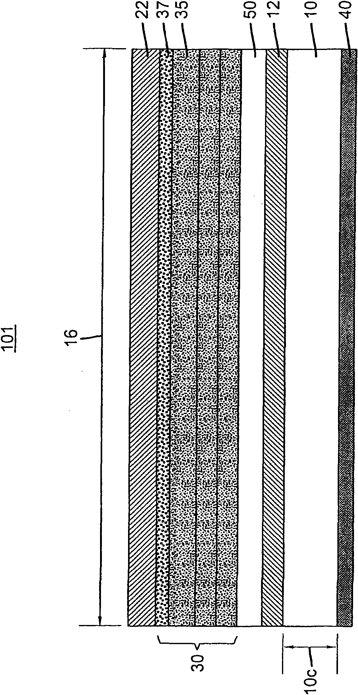
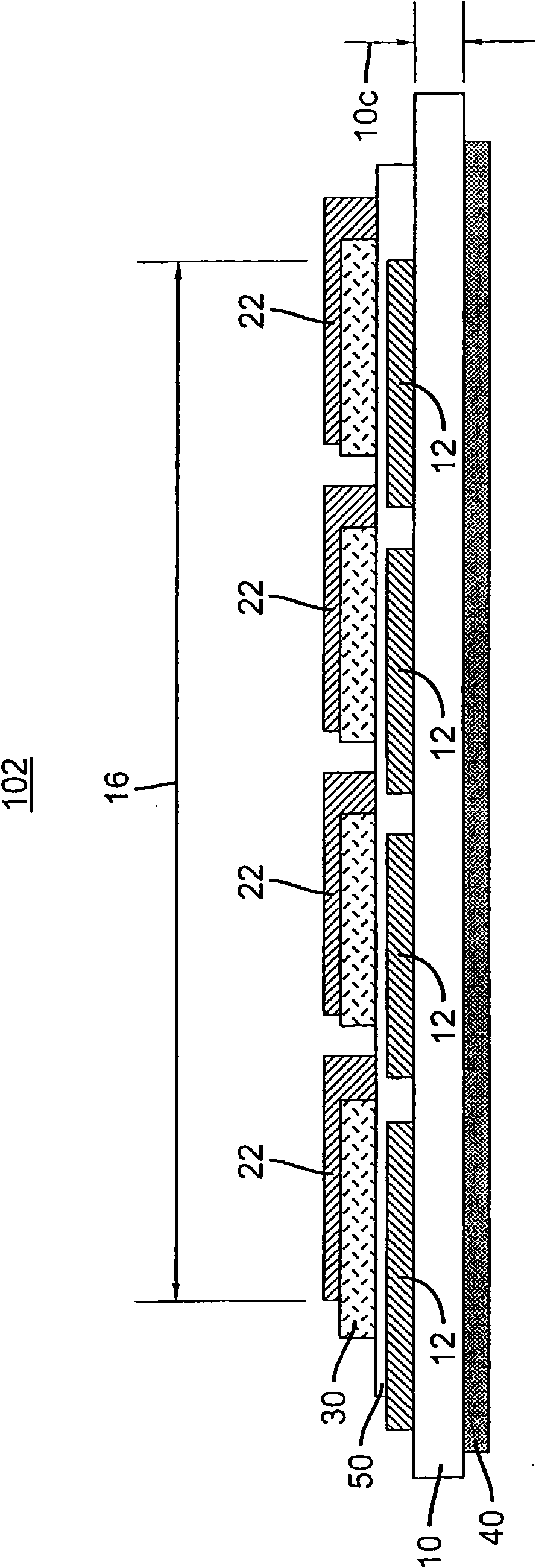
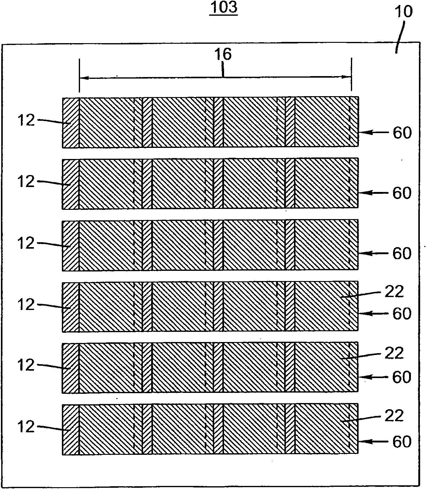
Provided is an OLED device including a transparent substrate having a first surface and a second surface, a transparent electrode layer disposed over the first surface of the substrate, a short reduction layer disposed over the transparent electrode layer, an organic light-emitting element disposed over the short reduction layer and including at least one light-emitting layer and a charge injection layer disposed over the light emitting layer, a reflective electrode layer disposed over the charge injection layer and a light extraction enhancement structure disposed over the first or second surface of the substrate; wherein the short reduction layer is a transparent film having a through-thickness resistivity of 10<-9> to 10<2>ohm cm<2>; wherein the reflective electrode layer includes Ag orAg alloy containing more than 80% of Ag; and the total device size is larger than 10 times the substrate thickness.

Description

Technical field [0001] The present invention relates to an electroluminescent device, in particular to a planar electroluminescent device structure for improving light output. Background of the invention [0002] The present invention relates to electroluminescent devices. Examples of electroluminescent devices include small molecule organic light emitting devices (SMOLED), polymer light emitting devices (PLED), and inorganic electroluminescent devices. The term "organic light emitting device (OLED)" refers to both small molecule organic light emitting devices and polymer light emitting devices. [0003] A typical prior art electroluminescent device includes a transparent substrate (its thickness is 1-4 orders of magnitude thicker than the remaining layers), a transparent first electrode layer, a light-emitting element, which includes at least one light-emitting layer, and a reflective The second electrode layer. When electrons and holes injected from the two electrodes flow thr...

Claims


Application Information

Patent Timeline
Patent Type & Authority Applications(China)
IPC IPC(8): H01L51/52
CPCH01L51/5096H01L51/5268H01L51/5234H01L2251/558H01L2251/306B82Y30/00B82Y20/00H01L2251/5369H10K2102/102H10K2102/331H10K2102/351H10K59/80518H10K59/877H10K59/878H10K50/18H10K50/854H10K50/828
Inventor 谭元昇D·R·普瑞斯G·法卢吉亚R·A·基索T·R·古许曼
Owner GLOBAL OLED TECH
Learn More