Coal gas small furnace of energy-saving durable type fuel generation furnace for glass tank furnace

A kind of furnace gas, durable technology, applied in glass production, glass furnace equipment, glass manufacturing equipment and other directions, can solve the problems of low service life, waste of energy, easy to burn out pre-combustion chamber wall, etc., to achieve long service life, Good energy-saving effect, beneficial to the effect of downward heat radiation

Inactive Publication Date: 2010-03-31
卢爱民
View PDF0 Cites 0 Cited by
  • Summary
  • Abstract
  • Description
  • Claims
  • Application Information

AI Technical Summary

Problems solved by technology

The inventor has found through long-term observation and research that the walls of the pre-combustion chamber are easily burned out, and the service life is often far below the design standard; in addition, part of the heat of the flame is not used on the glass material that should be heated, but is used on the glass material that should not be heated. On the wall of the preheating chamber, of course, energy will be wasted

Method used


Image

  • Coal gas small furnace of energy-saving durable type fuel generation furnace for glass tank furnace
  • Coal gas small furnace of energy-saving durable type fuel generation furnace for glass tank furnace
  • Coal gas small furnace of energy-saving durable type fuel generation furnace for glass tank furnace

Examples


Embodiment 1

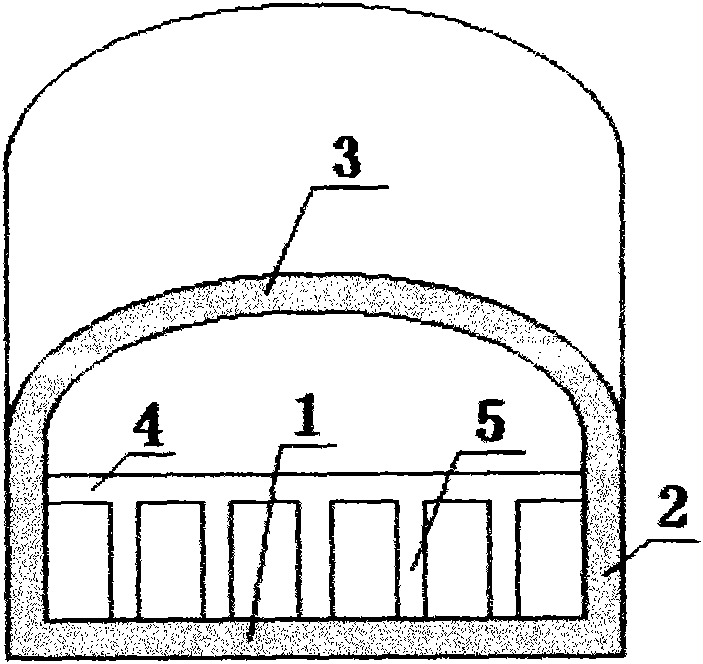
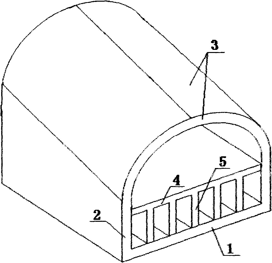
[0022] Embodiment one, such as figure 1 , 2 As shown in and 7, the energy-saving and durable gas-fired small furnace for the glass pool furnace of the present invention includes a bell-shaped longitudinal channel with a small front and a large rear that is composed of a bottom plate 1, two side walls 2 and an arched top wall 3, and the middle part of the longitudinal channel is An arched tongue 4 extending from the rear end to the front end is formed connecting the two side walls 2 , and the lower longitudinal channel separated by the tongue 4 is composed of six laterally juxtaposed sub-channels separated by the vertical partition 5 . The distance between the tongue 4 and the front end of the vertical partition 5 and the front end of the longitudinal channel is 0-800 mm. The top wall 3 or the top wall 3 and the tongue 4 are inclined downward from back to front. The entrance between the tongue 4 at the rear end of the longitudinal channel and the top wall 3 communicates with ...

Embodiment 2

[0023] Embodiment two, such as image 3 and 7 As shown in the present invention, the energy-saving and durable generator-fired small gas furnace for glass pool furnaces of the present invention comprises a trumpet-shaped longitudinal channel with a small front and a large rear formed by a bottom plate 1, two side walls 2 and an arched top wall 3. The middle part of the longitudinal channel is formed with a The flat plate-shaped tongue 4 extending from the rear end to the front end is connected to the two side walls 2, and the upper longitudinal channel separated by the tongue 4 is composed of four horizontally parallel sub-channels separated by the vertical partition wall 5 . The distance between the tongue 4 and the front end of the vertical partition 5 and the front end of the longitudinal channel is 0-800 mm. The top wall 3 or the top wall 3 and the tongue 4 are inclined downward from back to front. The entrance between the tongue 4 at the rear end of the longitudinal cha...

Embodiment 3

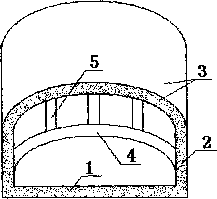
[0024] Embodiment three, such as Figure 4 and 7 As shown in the present invention, the energy-saving and durable generator-fired small gas furnace for glass pool furnaces of the present invention comprises a trumpet-shaped longitudinal channel with a small front and a large rear formed by a bottom plate 1, two side walls 2 and an arched top wall 3. The middle part of the longitudinal channel is formed with a The arched tongue 4 extending from the rear end to the front end connecting the two side walls 2, the upper and lower longitudinal channels separated by the tongue 4 are composed of four horizontally parallel sub-channels separated by the vertical partition walls 5 opposite up and down. The distance between the tongue 4 and the front end of the vertical partition 5 and the front end of the longitudinal channel is 0-800 mm. The top wall 3 or the top wall 3 and the tongue 4 are inclined downward from back to front. The entrance between the tongue 4 at the rear end of the ...


PUM


Abstract

The invention relates to a coal gas small furnace of an energy-saving durable type fuel generation furnace for a glass tank furnace, which solves the problems of short service life and low heat efficiency of the prior small furnace. The coal gas small furnace of the energy-saving durable type fuel generation furnace for the glass tank furnace comprises longitudinal passages which are in the shapeof a horn mouth, comprise a bottom plate, two side walls and a top wall and have small fronts and big backs, wherein the middle parts of the longitudinal passages are provided with tongues which are connected with the two side walls and extend from the back end to the front end, and at least one of an upper longitudinal passage and a lower longitudinal passage which are separated by the tongues comprises a plurality of transverse juxtaposed sub-passages separated by vertical partition walls. A distance among the tongues, the front ends of the vertical partition walls and the front ends of thelongitudinal passages is 0-800 millimeters. An inlet between the tongues at the back ends of the longitudinal passages and the top wall is communicated with a coal gas regenerative chamber of a generation furnace, and an inlet between the tongues and the bottom plate is communicated with a combustion-supporting air regenerative chamber. The invention has the advantages of little possibility of burning out, long service life, high heat efficiency and good energy-saving effect and is more beneficial to downward thermal radiation, a high-temperature combustion area moves to a glass melting tank forwards, and fuel gas is mixed fully.

Description

technical field [0001] The invention relates to a glass pool furnace, in particular to an energy-saving and durable generator gas small furnace for the glass pool furnace. Background technique [0002] The generator-fired gas small furnace (or pre-combustion chamber) used in the glass pool furnace is connected to the glass melting pool at the front end and the regenerator at the rear end; the generator-fired gas furnace is actually a small furnace that mixes gas and combustion-supporting air. The rear end of the regenerator is divided into upper and lower two ventilation channels by the tongue (the upper layer is an air channel, and the lower layer is a gas channel), and the front end of the glass melting tank is a fire channel without a tongue; the former is used to conduct Fuel gas, the latter is used to mix and ignite the two, and then spray into the glass melting pool to heat the glass material in the pool. Wherein the distance from the front end of the tongue to the fr...

Claims


Application Information

Patent Timeline
Patent Type & Authority Applications(China)
IPC IPC(8): C03B5/00
CPCY02P40/50
Inventor 卢爱民
Owner 卢爱民
Why Eureka
Try Eureka