Double temperature-sensing power-off circuit protection structure

A technology of inductive power failure and circuit protection, applied in the direction of protection switch operation/release mechanism, thermal switch components, heating/cooling contact switch, etc. And other issues

Inactive Publication Date: 2010-03-31
游聪谋
View PDF0 Cites 7 Cited by
  • Summary
  • Abstract
  • Description
  • Claims
  • Application Information

AI Technical Summary

Problems solved by technology

[0012] The present invention is to solve the problem that the existing temperature-sensing power-off protector has only one tripping power-off device with contact shrapnel as temperature induction, and cannot effectively set a power-off induction temperature value, and, when the current is overloaded and overheated, if the contact When the

Method used


Image

  • Double temperature-sensing power-off circuit protection structure
  • Double temperature-sensing power-off circuit protection structure
  • Double temperature-sensing power-off circuit protection structure

Examples


Embodiment Construction

[0058] In order to be able to disclose the purpose, characteristic and effect of the present invention in detail, hereby through the following preferred specific embodiments, in conjunction with the accompanying drawings, the present invention is described in detail as follows:

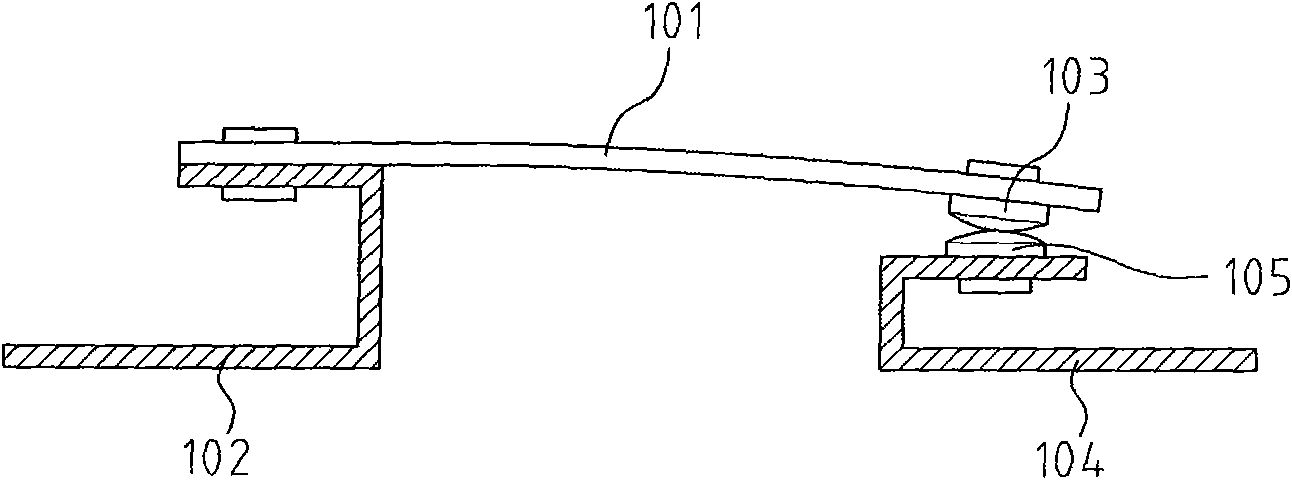
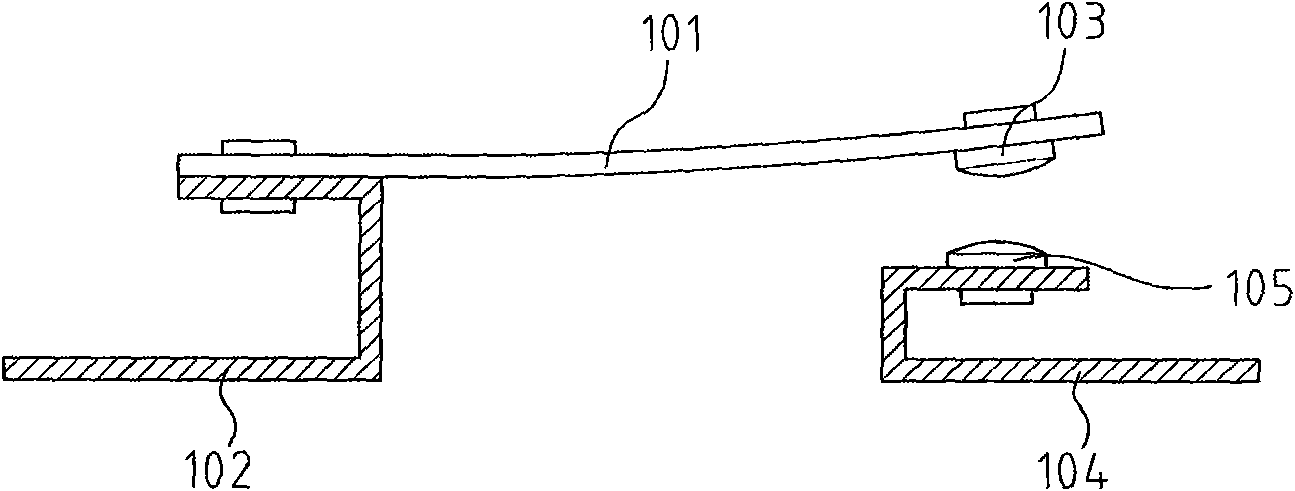
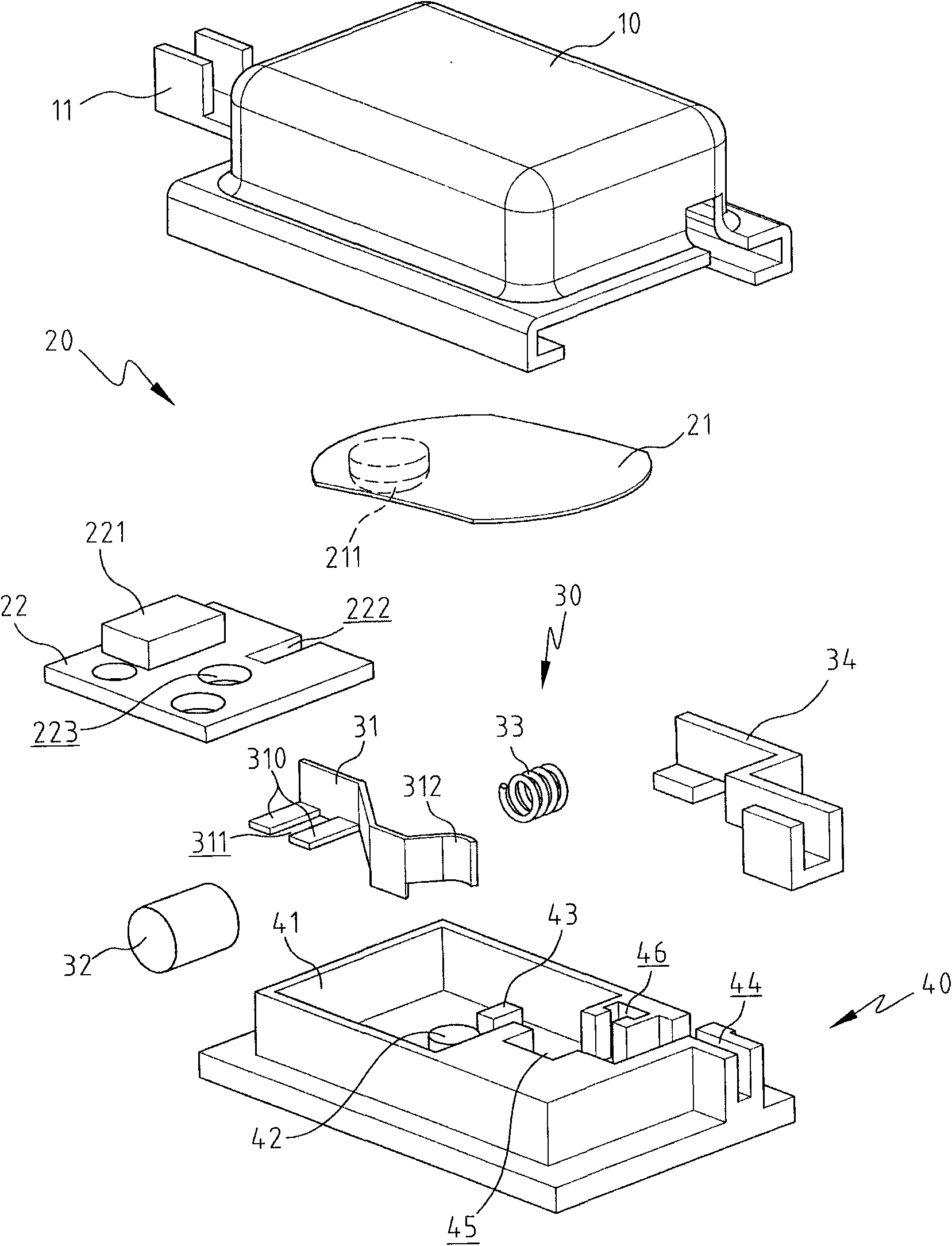
[0059] like Figures 3 to 6 As shown, it is a three-dimensional exploded view, a three-dimensional combined view, a combined cross-sectional view, and a combined cross-sectional view of the embodiment of the present invention, which shows the power-on (ON) schematic diagram of the embodiment of the present invention; a circuit protection structure of a dual temperature induction power-off of the present invention , including a cover body 10, a thermal induction tripping device 20, a thermal fuse device 30, and a seat 40; wherein,

[0060] The cover 10 is a conductor and is connected to a first terminal 11 .

[0061] The thermal induction tripping device 20 includes a contact elastic piece 21 and a co...


PUM


Abstract

The invention provides a double temperature-sensing power-off circuit protection structure, comprising two independently working temperature-sensing power-off devices arranged between two terminals ofa return circuit, a thermal sensing tripping device and a thermal breaking device. A contact striking flake of the thermal sensing tripping device is heated and deformed to reversely bend to trip outin order to realize interruption under the conditions of overload current, overheating circuits or excess high temperature of environment. Besides, when the thermal sensing tripping device fails to respond, respond late or repetitively powers off and the temperature of the return circuit continuously rises after powering on under the conditions of overload current, overheating circuits or excesshigh temperature of environment, a low-melting point block of the thermal breaking device is heated to be melted and broken in order to open the return circuit and realize interruption. In the invention, the two independently working temperature-sensing power-off devices respectively sense temperature, have a double temperature-sensing power-off effect, and the return circuit can be temporarily powered off, powered on again or completely powered off, thereby avoiding dangers of overheating circuits or short circuit of electric wires.

Description

technical field [0001] The present invention relates to a circuit protection structure for double temperature-sensing power-off, wherein a thermal-sensing tripping device and a thermal-fuse disconnecting device are arranged in the circuit loop to form two temperature-sensing power-off devices that operate independently; When the circuit is overheated or the ambient temperature is too high, the thermal induction tripping device is used to form a temporary power-off state that can be re-energized, or the fusible block of the thermal fuse device is further melted and broken to form a permanent circuit break (OFF) state. Background technique [0002] The use of electricity is an indispensable part of modern human society. All kinds of electrical products and equipment surround life, especially computerized and information-based industries, home, transportation, education, entertainment, etc., even without electricity. On the other hand, the safe use of electricity is something ...

Claims


Application Information

Patent Timeline
IPC IPC(8): H01H37/76H01H37/46H01H71/14H01H71/20
Inventor 游聪谋
Owner 游聪谋
Why Eureka
Try Eureka