
Rear projection system

A technology of rear projection and projection objective lens, applied in the field of rear projection system, can solve the problems of low contrast, large depth and volume, etc., to achieve the effect of thinning, reducing stray light, and changing the contrast is not high

Inactive Publication Date: 2010-03-31
SHENZHEN KECHUANG DIGITAL DISPLAY TECH
View PDF0 Cites 0 Cited by
  • Summary
  • Abstract
  • Description
  • Claims
  • Application Information

AI Technical Summary

Problems solved by technology

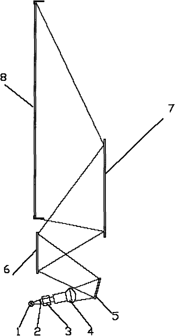
[0005] The purpose of the present invention is to provide a rear projection system, through the projection objective lens and two curved mirrors to achieve the purpose of thinning the rear projection system, and at the same time use the diaphragm to achieve the best optical contrast of the rear projection system, which can overcome the disadvantages of the existing rear projection system Large depth volume and low-contrast defects make the rear projection system thinner

Method used


Image

  • Rear projection system
  • Rear projection system
  • Rear projection system

Examples


Embodiment Construction

[0023] In order to further illustrate the technical means adopted by the present invention and its decorative effect, the following is a detailed description in conjunction with preferred embodiments of the present invention and accompanying drawings.

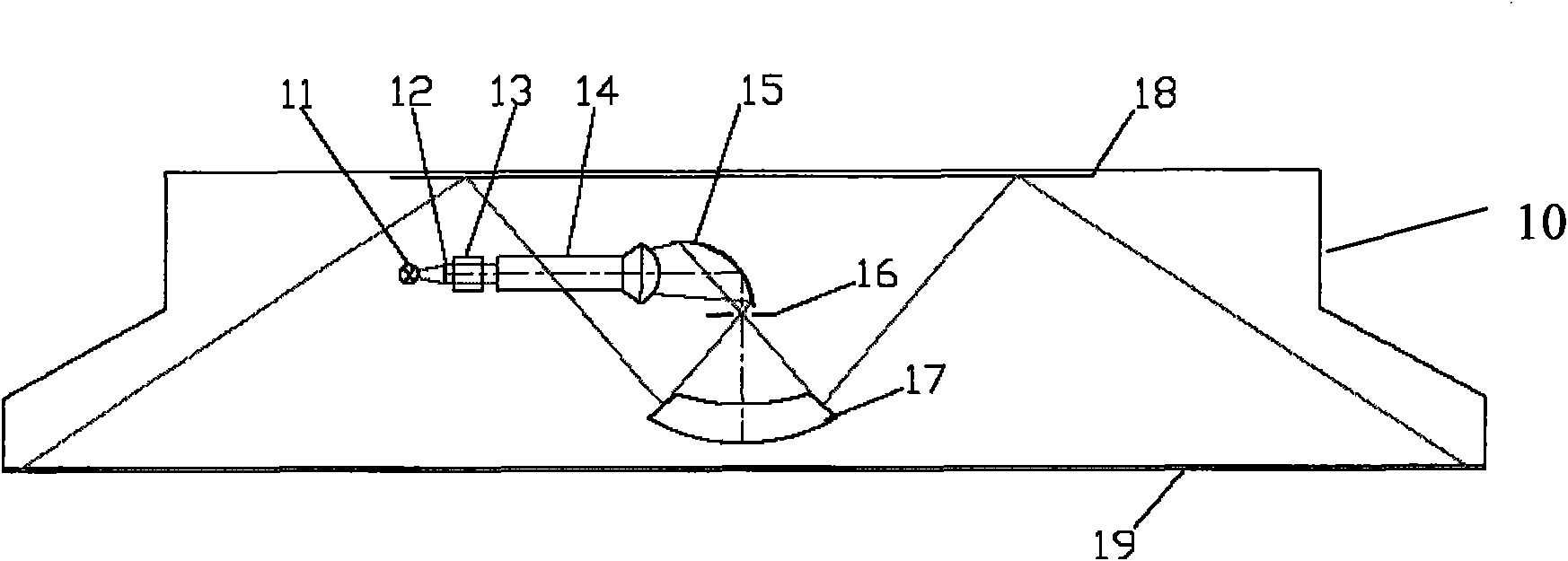
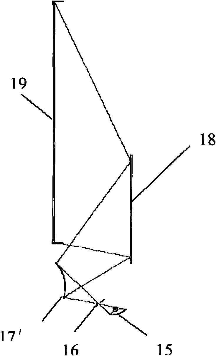
[0024] Such as figure 2 As stated, the rear projection system of the present invention includes: an imaging device, a projection objective lens 14, a first concave reflector 15, a second curved reflector 17, a plane reflector 18 and a projection screen 19, and the imaging device includes a correspondingly arranged display light source 11 , the display component 12 and the optical prism 13 . The first concave reflector 15 is placed on the optical axis of the projection objective lens 14, the second curved reflector 17 is placed on the reflected light path of the first concave reflector 15, and the plane reflector 18 is arranged on the reflected light of the second curved reflector 17 On the road, the projection screen 19 is ar...


PUM


Abstract

A rear projection system comprises an image device, a projection lens, a first concave reflector, a second curve reflector, a reflecting mirror and a projection screen; wherein the projection lens isarranged corresponding to the image device, the first concave reflector is arranged on the optical axis of the projection lens, the second curve reflector is arranged on the reflected light path of the first concave reflector, the reflecting mirror is arranged on the reflected light path of the second curve reflector, and the projection screen is arranged corresponding to the reflecting mirror; and the image device irradiates onto the first concave reflector by the projection lens and then is reflected to the second curve reflector, and the image of the second curve reflector arrives at the projection screen by reflecting of the reflecting mirror. The rear projection system of the invention achieves rear projection system thinning by the projection lens and two curve reflectors, and meanwhile diaphragm is utilized to achieve optimal optical contrast of rear projection system, the problem that the existing rear projection system has the defects of large depth volume and low contrast canbe solved, so as to realize thinning of rear projection system.

Description

technical field [0001] The invention relates to the technical field of projection, in particular to a rear projection system. Background technique [0002] Rear projection system (for example: rear projection TV) used to be the mainstream of large-size TV when CRT occupied the mainstream of the market. Rear projection system manufacturing large-screen display has many advantages compared with CRT large-screen display, such as: light weight, relative depth Wait a minute. However, when flat panel TVs (such as LCD and PDP) gradually began to develop from small and medium sizes to larger sizes, many CRT manufacturers, especially those in mainland China, were looking for industrial transformation and upgrading to catch up with market trends. The improvement work of volume is then not deepened, therefore, the rear projection system is gradually abandoned by people because of its larger volume. [0003] Such as figure 1 Shown is the existing rear projection system, including: di...

Claims


Application Information

Patent Timeline
Patent Type & Authority Applications(China)
IPC IPC(8): H04N13/00H04N13/04G02B17/08G02B7/182G02B5/10
Inventor 李方红韩政伟汤波
Owner SHENZHEN KECHUANG DIGITAL DISPLAY TECH
Learn More