
Singlechip LCD projector

A projector and single-chip technology, applied in the field of projectors, can solve problems such as poor heat dissipation performance of LCD light valves, reduce useless space of projectors, affect image quality, etc., and achieve improved market competitiveness, good image color uniformity, Reduce the effect of packaging

Pending Publication Date: 2019-04-12
CHANGSHA CRE ELECTRONICS TECH CO LTD
View PDF1 Cites 6 Cited by
  • Summary
  • Abstract
  • Description
  • Claims
  • Application Information

AI Technical Summary

Problems solved by technology

The existing single-chip LCD projectors have two structural forms, direct-projection and reflective-type according to the structure of the optical path. Among them, the direct-projection single LCD projector has a large shape, low volume utilization rate, and outdated shape. , which is rarely seen in the market now; reflective single LCD projectors, such as a single-chip LCD projector disclosed in patent document CN201810522555.0, can significantly reduce the The length of the projector is reduced to reduce the useless space inside the projector. Under the same conditions, the volume of the projector is made smaller, but the heat dissipation performance of the LCD light valve is poor, and the performance requirements for the mirror coating are extremely high, otherwise the reflection performance is poor. The color uniformity of the image projected on the screen is poor, which affects the image quality and the practical effect is relatively limited

Method used


Image

  • Singlechip LCD projector
  • Singlechip LCD projector
  • Singlechip LCD projector

Examples


Embodiment 1

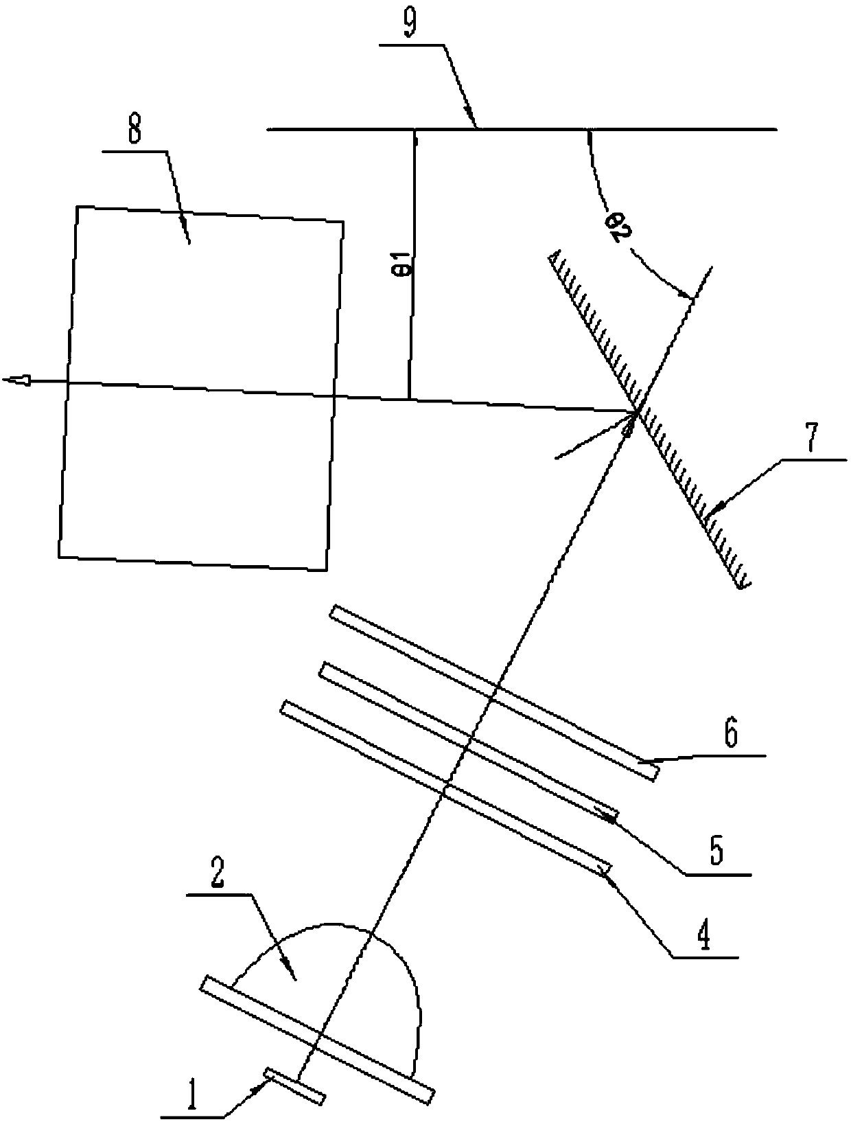
[0024] Such as figure 1 As shown, a kind of single-chip LCD projector provided by the present invention comprises LED light source 1, condenser lens 2 (or hollow square cone light pipe), collimating lens 4, LCD light valve 5, field lens 6 and projection lens 8, The LCD light valve 5 is arranged between the collimator 4 and the field lens 6, the condenser lens 2 is arranged between the LED light source 1 and the collimator 4, and the projection lens 8 is arranged in the field Behind the mirror 6; between the field mirror 6 and the projection lens 8 is a reflector 7; the reflector 7 is mirrored along its long axis.

[0025] In this embodiment, a reflector 7 is arranged between the field mirror 6 and the projection lens 8. Compared with the existing direct projection type single-chip LCD projector, its volume is more compact, and the reflector 7 is arranged along its long axis. Compared with the existing reflective single-chip LCD projectors, the layout method of mirror reflecti...

Embodiment 2

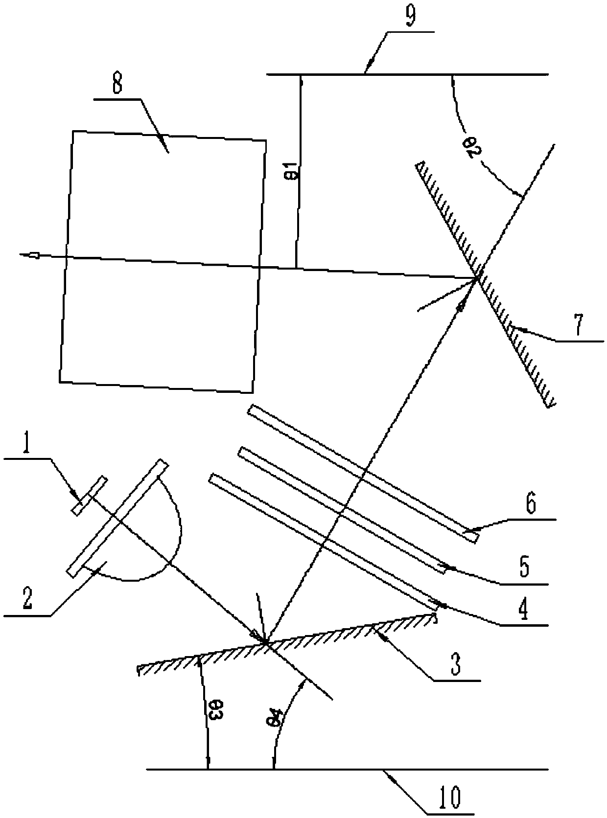
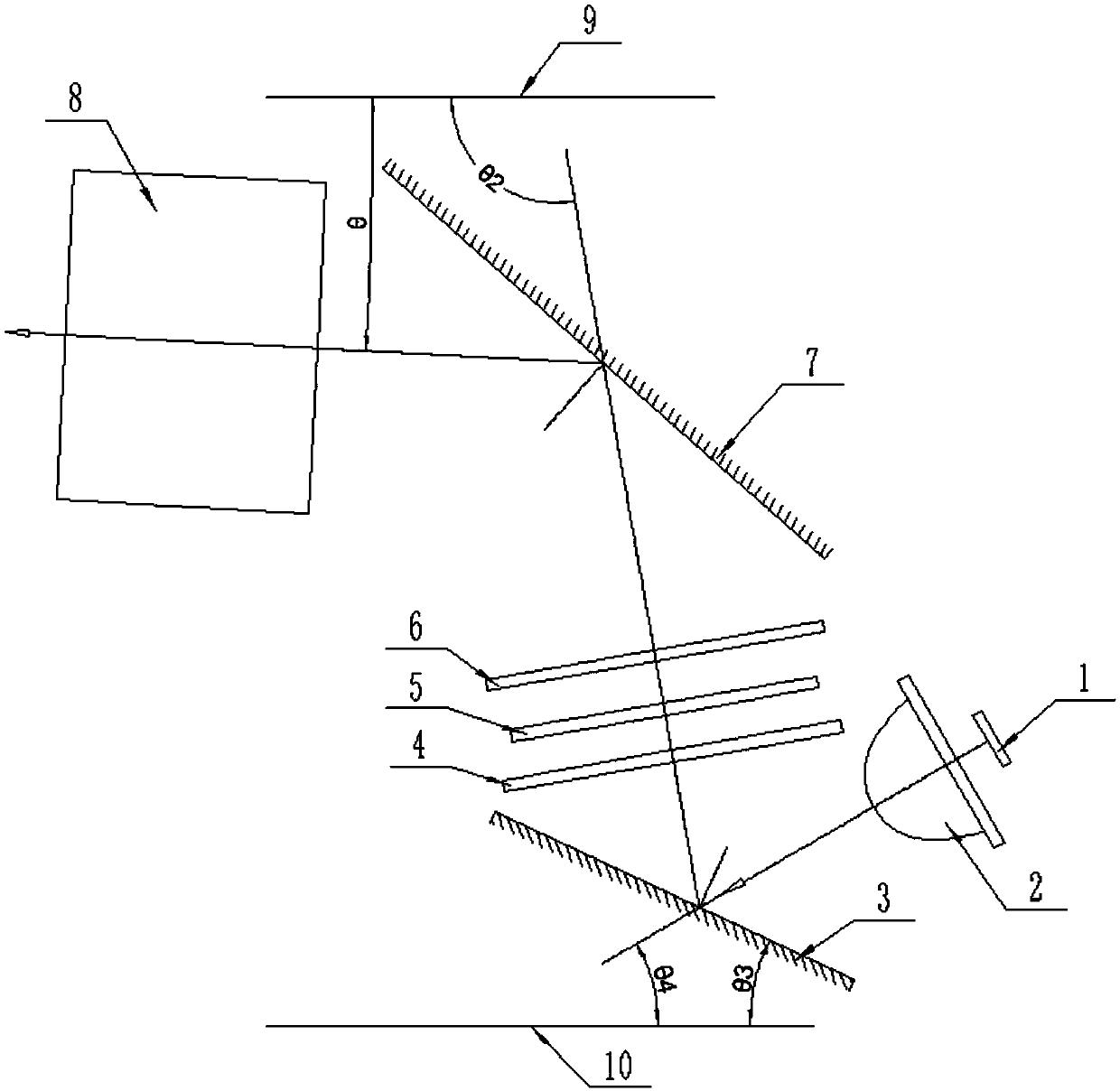
[0027] Such as figure 2 and 3 As shown, a kind of single-chip LCD projector provided by the present invention includes LED light source 1, condenser lens 2, collimator lens 4, LCD light valve 5, field lens 6 and projection lens 8, and described LCD light valve 5 is located at the Between the collimating lens 4 and the field lens 6, the condenser lens 2 is arranged between the LED light source 1 and the collimating lens 4, and the projection lens 8 is arranged behind the field lens 6; the condenser lens 2 A mirror two 3 is provided between the collimating mirror 4, and a mirror one 7 is provided between the field mirror 6 and the projection lens 8, and the mirror two 3 is mirrored along its long axis, so The mirror one 7 is a mirror reflection along its long axis.

[0028] In this embodiment, reflective mirror 2 3 is provided between condenser mirror 2 and collimating mirror 4, and reflective mirror 1 7 is provided between field mirror 6 and projection lens 8, compared with ...


PUM


Abstract

The invention discloses a singlechip LCD projector. The singlechip LCD projector comprises an LED light source, a collecting lens, a collimating mirror, an LCD light valve, a field lens and a projection lens, wherein the LCD light valve is arranged between the collimating mirror and the field lens, the collecting lens is arranged between the LED light source and the collimating mirror, the projection lens is arranged at a rear surface of the field lens, a first reflecting mirror is arranged between the field lens and the projection lens and is in mirror image along a long axis of the first reflecting mirror. The singlechip LCD projector has the characteristics of small size, novel appearance, good image color uniformity, good cooling performance, long service lifetime and the like.

Description

technical field [0001] The invention relates to the technical field of projectors, in particular to a single-chip LCD projector. Background technique [0002] A single-chip LCD projector refers to a projector product that uses a full-color, transmissive liquid crystal screen (LCD) as the light valve, based on Kohler lighting, and projects the image of the light valve on the screen through a projection lens. The existing single-chip LCD projectors have two structural forms, direct-projection and reflective-type, according to the different optical path structures. Among them, the direct-projection single LCD projector has a large shape, low volume utilization rate, and outdated shape. , which is rarely seen in the market now; reflective single LCD projectors, such as a single-chip LCD projector disclosed in patent document CN201810522555.0, can significantly reduce the The length of the projector is reduced to reduce the useless space inside the projector. Under the same cond...

Claims


Application Information

Patent Timeline
IPC IPC(8): G03B21/00G03B21/28G03B21/20G03B21/16
CPCG03B21/006G03B21/16G03B21/2066G03B21/28
Inventor 陈灵
Owner CHANGSHA CRE ELECTRONICS TECH CO LTD
Learn More