Slag rise preventing method, and punch mold

A punch and scrap technology, applied in the direction of piercing tools, nibbling cutting devices, shearing devices, etc., can solve the problems of blowing to the workpiece, punching waste blowing into the die hole 27, etc., to achieve The effect of preventing rising

Inactive Publication Date: 2010-03-31
AMADA CO LTD +1
View PDF3 Cites 2 Cited by
  • Summary
  • Abstract
  • Description
  • Claims
  • Application Information

AI Technical Summary

Problems solved by technology

And, after punching edge 13 rises to proper position, when punching waste material falls naturally, can cause punching waste material t

Method used


Image

  • Slag rise preventing method, and punch mold
  • Slag rise preventing method, and punch mold
  • Slag rise preventing method, and punch mold

Examples


Embodiment Construction

[0048] Hereinafter, embodiments of the present invention will be described with reference to the drawings, wherein the same symbols are assigned to the structures that can realize the same functions as the above-mentioned conventional structures, and the description is omitted.

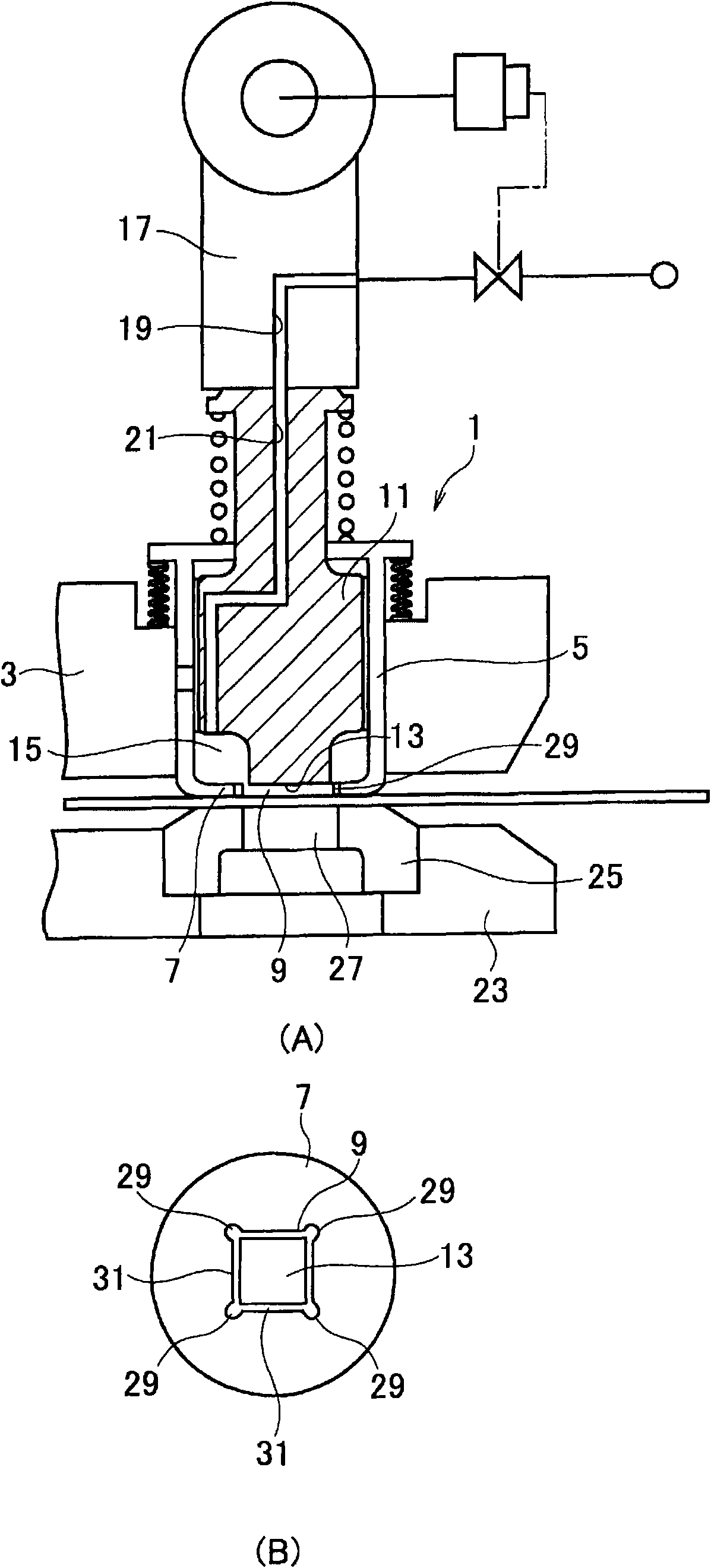
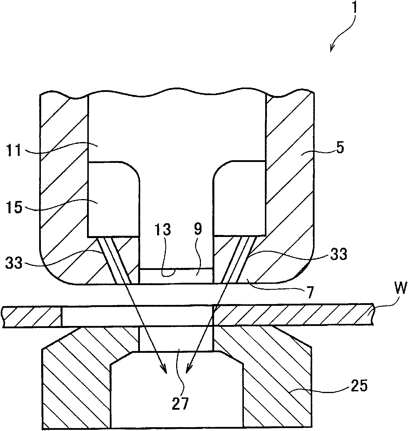
[0049] as expressed conceptually and roughly figure 2 According to the structure of the punch and die of the present invention, it is substantially the same as the aforementioned punch 1 and die 25. That is, the punch 1 has a cylindrical punch guide 5 , and the lower portion of the punch guide 5 has a plate pressing portion 7 . Further, a plurality of fluid ejection holes 33 communicating with the annular space 15 are formed around the through hole 9 in the upward direction of the plate pressing portion 7 . The fluid ejection holes 33 are set in a non-communicating state not directly connected to the through hole 9, and point to an obliquely downward direction so as to eject fluid from each fluid ej...


PUM


Abstract

Provided are a slag rise preventing method at the time when a plate-shaped work (W) is punched by the coaction between a punch mold (1) and a die mold (2), and a punch mold. In the slag rise preventing method, the work is pushed onto the upper face of the die mold by a plate holder (7) belonging to the punch mold. A portion of the work is pushed into a die hole (27) in the die mold by a punch blade portion (13) belonging to the punch mold. At the rising time of the punch blade portion (13) when the punch blade portion is positioned on the upper side of the lower face of the work and on the lower side of the upper face of the work, a liquid is blown in a large quantity from a hole portion already formed in the work toward the lower side of the punch blade portion (13), thereby to drop smallpieces of slag positioned on the lower side of the punch blade portion, into the die hole (27).

Description

technical field [0001] The present invention relates to a method and application for preventing scrap from floating up to the workpiece when punching a plate-shaped workpiece using, for example, a turret punch press using a punch and a die of the punch press. Convex mold for this method. Background technique [0002] Conventionally, when punching a plate-shaped workpiece with a punch and a die included in a punching machine, the blank to be punched out (punching scrap) adheres closely to the punch main body that moves up and down on the punch. Below the punch cutting edge at the lower end, the blanking scrap rises integrally with the punch main body when the punch main body rises, causing the punching scrap to rise above the workpiece. Conventionally, in order to prevent scrap from rising, the structure of the inner peripheral surface of the die hole is finely machined to hold the blank on the inner peripheral surface of the die hole of the die, or a structure in which flui...

Claims


Application Information

Patent Timeline
IPC IPC(8): B21D28/00
CPCB23D27/00B21D45/006B21D28/14B21D28/34B21D45/003Y10T83/0453Y10T83/2066B21D28/00B21D45/00
Inventor 冈本拓也
Owner AMADA CO LTD
Why Eureka
Try Eureka