
Separation mechanism of on-board equipment

A technology for separating mechanisms and equipment, which is applied in the satellite and aerospace fields, can solve problems such as poor product versatility, poor tape versatility, complex system composition, etc., and achieve the effects of reducing the difficulty of machining, large mechanism bearing capacity, and flexible installation positions

Active Publication Date: 2010-04-07
AEROSPACE DONGFANGHONG SATELLITE
View PDF0 Cites 34 Cited by
  • Summary
  • Abstract
  • Description
  • Claims
  • Application Information

AI Technical Summary

Problems solved by technology

[0005] (1) The use environment is limited. According to the working principle of the satellite-rocket separation tape, the shape of the connected spacecraft at the joint can only be a cylinder, which makes the shape and structure of the spacecraft at the joint subject to strict restrictions. Restrictions, so that the use environment of the separate tape is limited;
[0006] (2) The machining accuracy of the connection surface is too high. According to the current use of the star-rocket separation tape, it can be seen that it puts forward higher requirements for the machining accuracy of the star-rocket separation surface of satellites and rockets. The processing process brings difficulties;
[0007] (3) The versatility between products is poor. Due to the characteristics of the structure of the Star-Arrow Separation Tape itself, the versatility between different types of straps is poor;
[0008] (4) The composition of the system is complex. Due to the limitations of the design principle and the use environment, the composition of the star-arrow separation tape system is still very complicated, and the assembly and debugging process of the entire system before use will take a long time

Method used


Image

  • Separation mechanism of on-board equipment
  • Separation mechanism of on-board equipment
  • Separation mechanism of on-board equipment

Examples


Embodiment Construction

[0041] The present invention is specifically described by using a typical single set of on-board equipment separation mechanism. As for the specific selection of several sets of compression and release mechanisms in the specific application process, it should be determined according to the shape and requirements of the target load.

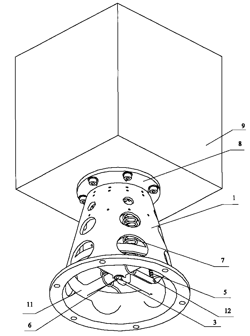
[0042] figure 1 It is a perspective view during the implementation of the present invention, figure 1 The square equipment in the middle and upper part is the simulated target load 9, and the lower structure of the target load 9 is the on-board equipment separation mechanism of the present invention.

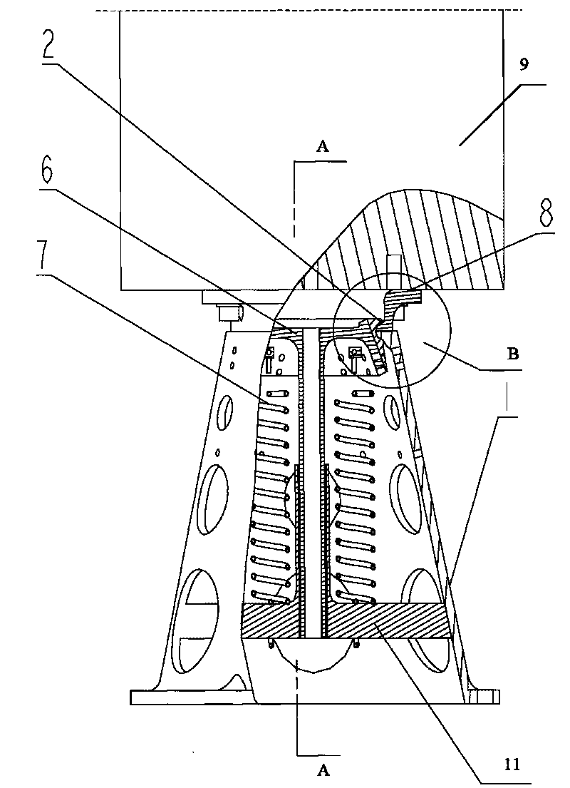
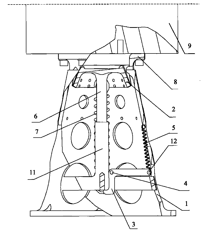
[0043] Such as Figure 2-5As shown, the present invention includes an installation base body 1, several pressing clamp blocks 2, a connecting flange 8, a pressing and releasing mechanism and an unlocking device. The compression and release mechanism includes a connecting shaft 6 and a connecting spring 7, and the unlocking device includes a dead b...


PUM


Abstract

The invention relates to a separation mechanism of on-board equipment, comprising a mounting base body, a plurality of compressing clamping blocks, a connecting flange, a compressing and releasing mechanism and an unlocking device; the compressing and releasing mechanism comprises a connecting shaft and a connecting spring, the unlocking device comprises a locking dog, a locking dog shaft, a tension spring, a pre-tightening rope and a flame cutter; the locking dog is adopted to lead the direction of the pre-tightening force of the mechanism, directly acted on the compressing clamping block, to be changed, so as to lead the direction of the pre-tightening force to be downwards; the force is transmitted to the compressing clamping block by the connecting shaft, and the structure is simpler and is easier to realize compared with the prior art; in the invention, a compression matching way of the compressing clamping blocks is adopted without high precision of a space vehicle or target load at the connecting position for separation, thereby effectively reducing the machining difficulty of the space vehicle or the target load at the connecting position for separation; a way that multiple groups are matched is adopted, so as to achieve the using requirements of universalization, modularization and serialization.

Description

technical field [0001] The invention relates to a separation mechanism for on-board equipment, which belongs to the technical field of satellites and aerospace. Background technique [0002] Satellites or other spacecraft often need to complete some compression and release actions according to mission requirements or due to some constraints, such as the on-orbit separation between the parent body and the daughter body, the individual and the main body, etc. The completion of such actions is through complex To achieve this, the mechanism system must not only ensure that the spacecraft provides reliable constraints for the target load on the ground and during flight, but also ensure that the spacecraft can safely and reliably separate the target load after it enters orbit. [0003] Compression and release are the two most important functions in this type of mechanism system, and they are also the two most critical force-bearing links. Compression means that the spacecraft con...

Claims


Application Information

Patent Timeline
IPC IPC(8): B64G1/64
Inventor 王培明刘森王海明
Owner AEROSPACE DONGFANGHONG SATELLITE
Learn More