Method and system for enhancing refresh rate of video display of light-emitting diode

A light-emitting diode and video display technology, applied to light sources, electric light sources, static indicators, etc., to achieve the effects of low cost, increased control area, and increased refresh rate

Active Publication Date: 2010-04-07
深圳康佳控股集团有限公司
View PDF3 Cites 8 Cited by
  • Summary
  • Abstract
  • Description
  • Claims
  • Application Information

AI Technical Summary

Problems solved by technology

[0004] Therefore, the existing technology

Method used


Image

  • Method and system for enhancing refresh rate of video display of light-emitting diode
  • Method and system for enhancing refresh rate of video display of light-emitting diode
  • Method and system for enhancing refresh rate of video display of light-emitting diode

Examples


Embodiment 1

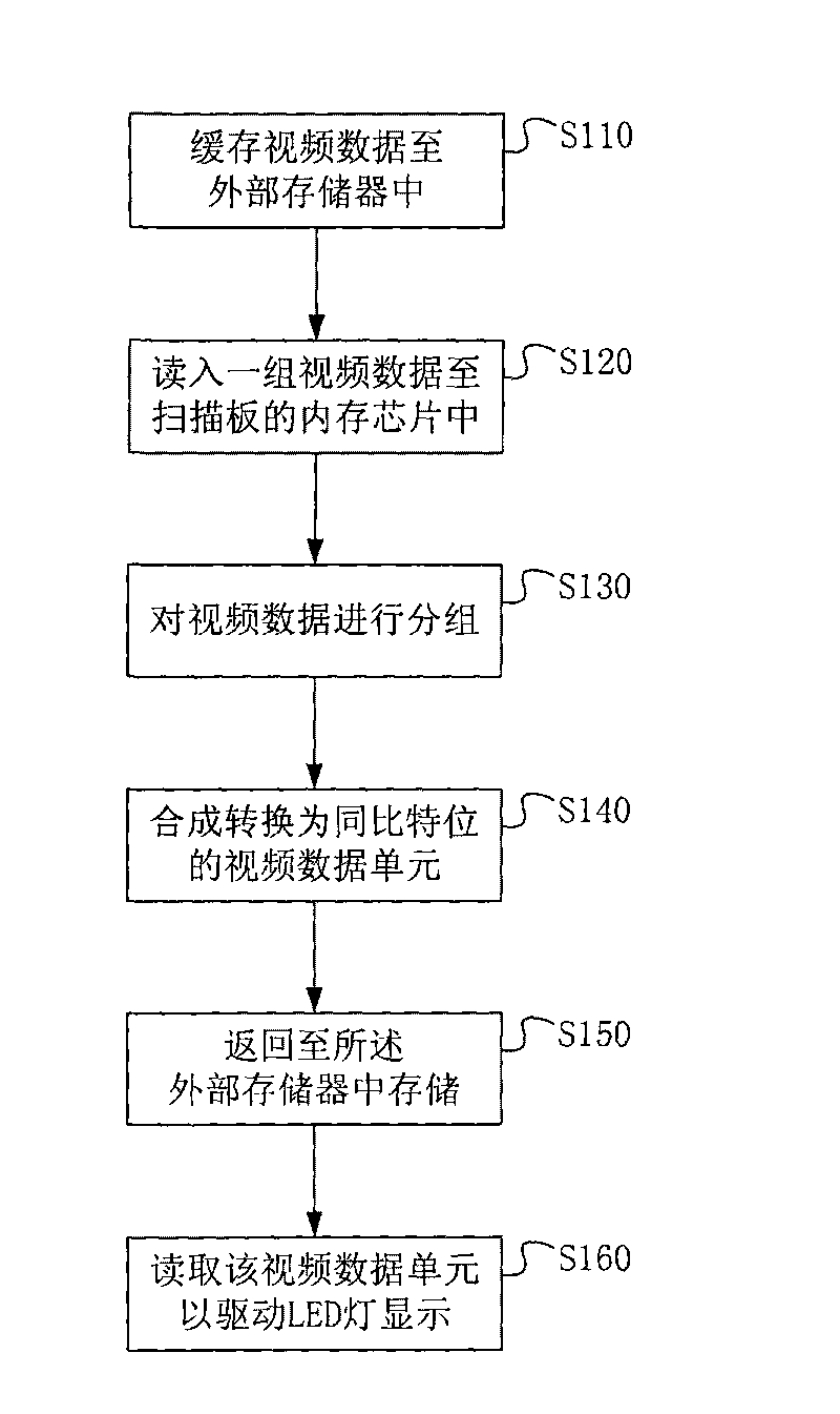
[0060]Embodiment 1. Taking each scanning board as an example with 16 data channels, when all the video data of one frame is buffered into the external memory, these data are read into the memory chip of the scanning board according to the set order Among them, the number of data points read in each time is equal to the number of data channels on the scanning board, that is, 16 points of 16-bit video data are read in from the external memory each time, and the bit comes from binarydigit, which is transliterated into bits and is used To describe the smallest unit of computer data, for example, in the binary number system, each 0 or 1 is a bit; and each point contains the gray levels of R, G, and B. This 16×3 =48 video data of 16bit are stored separately after grouping according to R, G and B; when one group of 16bit video data is read into the buffer area of ​​the memory chip of the scanning board, each 16bit video data is divided into bits Units for data conversion, as attached...

Embodiment 2

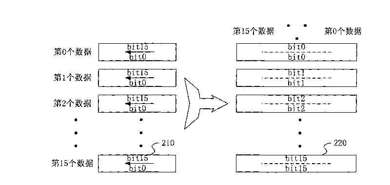
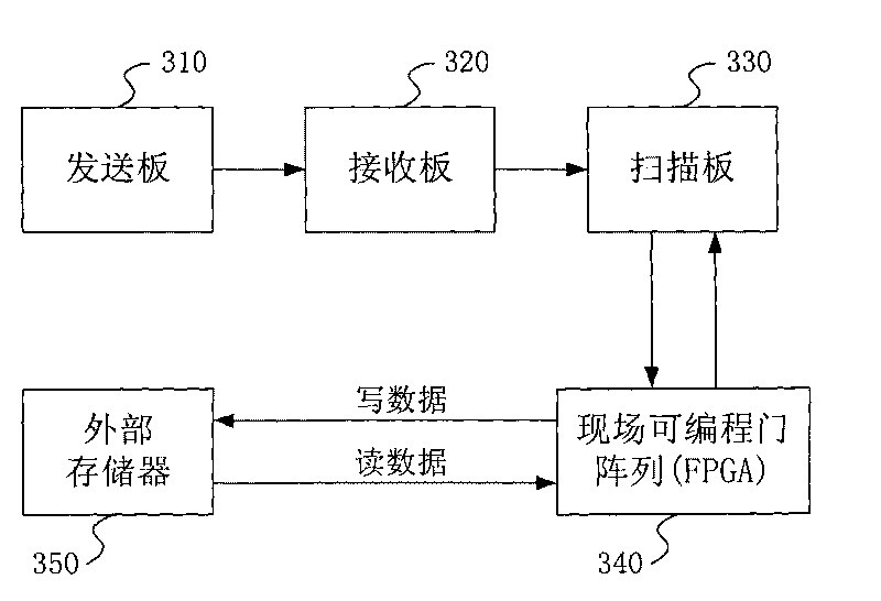
[0065] Embodiment two, at first the video data of a frame or part of the video data are stored in the external memory through the FPGA, and then the appropriate video data is read into the FPGA, and the video data to be transmitted to the large LED display screen Each 16 pieces of data are divided into one group, that is, 16 pieces of 16-bit video data are all allocated to the inside of the FPGA chip to form a 16×16 video data unit; at this time, the conversion of the 16×16 video data unit is started : First take out the 0th data to the 15th 0bit, a total of 16 0bits and reassemble the first 16-bit video data; then take out the 0th data to the 15th 1st bit, a total of 16 1bits The bits are recombined into the second 16-bit video data; finally, a total of 16 15-bit bits are taken out from the 0th data to the 15th 5th bit and reassembled into the 16th 16-bit video data, thus forming a new 16×16 video data; when transmitting the video data to the large LED display screen, the new...


PUM


Abstract

The invention discloses a method and a system for enhancing the refresh rate of the video display of a light-emitting diode, wherein the method comprises the steps: caching video data to an external memory in a set order; reading the video data therefrom which is equivalent to the number of data channels on a scanning panel; combining and converting the same bit of the video data video data units arrayed at the same bit; reading the combined and converted video data to drive the light-emitting diode in the scanning panel to emit light so as to display the video. As the video data structure originally comprising a plurality of bits is converted into the video data structure with the same bit and the external memory having relatively low cost is utilized, the video data, with the same bit, of all the channels on the scanning panel is read out in parallel each time the video data is read when the scanning panel uses a pulse width modulation way for driving, which is to say, the control area of the scanning panel is increased in order to indirectly enhance the refresh rate of the video display of the light-emitting diode.

Description

technical field [0001] The present invention relates to the method and system field of LED video display control, and more specifically, the improvement relates to a method and system for increasing the refresh rate of LED video display. Background technique [0002] A control system of a large LED (Light Emitting Diode, hereinafter referred to as LED) screen generally requires a sending board, a receiving board and several scanning boards. The larger the control range of the scanning board, the more points each scanning board scans, and the fewer scanning boards are required for the entire LED large screen; on the contrary, the more scanning boards are required. Therefore, by increasing the control range of the scanning boards, the number of scanning boards can be reduced, thereby reducing the cost of the entire control system. In today's market competition, for manufacturers of LED large screens, cost will be particularly important. [0003] However, if the control area ...

Claims


Application Information

Patent Timeline
IPC IPC(8): G09G3/32H05B37/02
Inventor 庞凤江
Owner 深圳康佳控股集团有限公司
Why Eureka
Try Eureka