Structure for fastening amorphous alloy transformer body and method for assembling transformer body

A fastening structure, amorphous alloy technology, applied in the direction of transformer/inductor coil/winding/connection, inductance/transformer/magnet manufacturing, electrical components, etc., can solve problems such as unsuitable assembly methods, and improve short-circuit resistance , reduce noise, and avoid the effect of iron core stress

Inactive Publication Date: 2010-04-07
INST OF ELECTRICAL ENG CHINESE ACAD OF SCI +1
View PDF0 Cites 12 Cited by
  • Summary
  • Abstract
  • Description
  • Claims
  • Application Information

AI Technical Summary

Problems solved by technology

However, due to the mechanical characteristics of the amorphous alloy material, it is not suitable for the assembly method of this insert. At the same time, the iron core of the traditional shell-type transformer is compressed by the middle fuel tank and the lo

Method used


Image

  • Structure for fastening amorphous alloy transformer body and method for assembling transformer body
  • Structure for fastening amorphous alloy transformer body and method for assembling transformer body
  • Structure for fastening amorphous alloy transformer body and method for assembling transformer body

Examples


Embodiment Construction

[0027] The present invention will be further described below in conjunction with the accompanying drawings and specific embodiments.

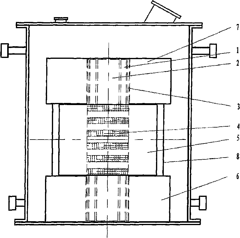
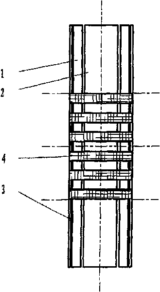
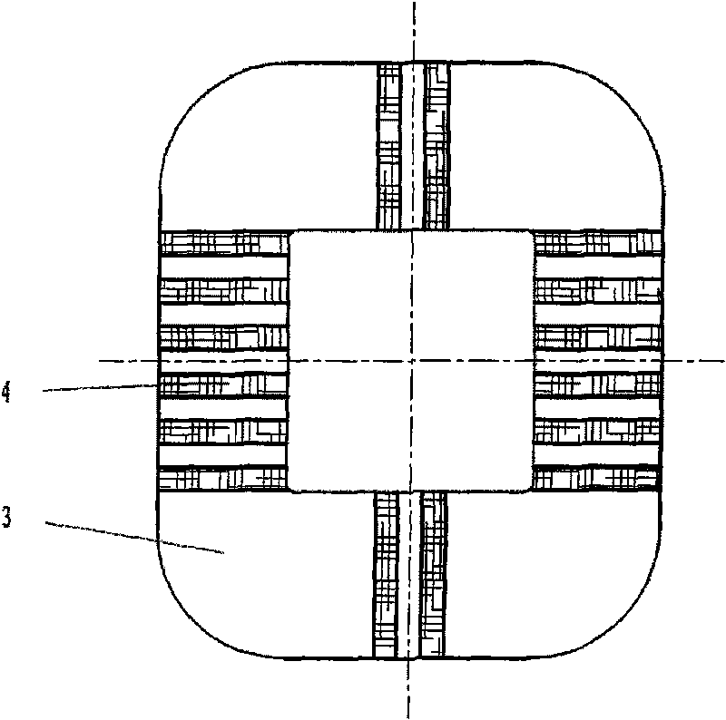
[0028] The body fastening structure of the amorphous alloy transformer of the present invention includes a low-voltage coil 1, a high-voltage coil 2, a pressure plate 3, a binding strap 4, a core column 5, a lower clamp 6, an upper clamp 7, and a limit rod 8. The phase windings are alternately arranged in the form of a low-voltage coil and a high-voltage coil. The pressure plate 3 is placed outside the coil at the end of the phase winding, and the phase winding and the pressure plate 3 are fastened by a binding band 4 to form an independent fastened coil. Phase winding; one or more phase windings are set on the core column; the lower and upper parts of the coils in the phase winding are respectively embedded in the grooves of the lower fixture and the upper fixture, and the spacers are used between the pressure plate and the walls of the upper a...


PUM


Abstract

The invention provides a structure for fastening an amorphous alloy transformer body. A low-voltage coil (1) and a high-voltage coil (2) in a phase winding of the transformer body are distributed in a staggered manner; a clamp plate (3) is arranged on the outer side of the end part of the phase winding of the transformer body; one or a plurality of phase windings are sleeved on a core limb (5); the phase windings are fastened by a binding tape (4); and the upper parts and the lower parts of the coils in the phase windings are embedded in the grooves of a lower fixture (6) and an upper fixture (7) respectively. The method for assembling the transformer body comprises the following steps: winding the low-voltage coil (1) and the high-voltage coil (2) respectively; assembling the coils into a single phase winding; tightly pressing the phase windings inwards by the clamp plate (3); binding up the phase windings and the clamp plate (3) by the binding tape (4); sleeving the bound phase windings on the core limb (5); mounting the phase windings together with the core limb (5) on the upper fixture (7) and the lower fixture (6); and plugging cushion blocks between the clamp plate (3) and the walls of the upper fixture (7) and the lower fixture (6).

Description

technical field [0001] The invention relates to a structure for fastening an amorphous alloy transformer body and an assembly method thereof. Background technique [0002] Amorphous alloy transformer is an excellent low-loss energy-saving transformer. It is characterized by the use of amorphous alloy materials instead of silicon steel sheets to make iron cores, which makes the transformer's no-load loss and no-load current small, so it has received more and more attention. attention. However, because amorphous alloy materials are very sensitive to mechanical stress, commonly known as metallic glass, both tensile stress and bending stress will affect their magnetic properties, so the short-circuit resistance of amorphous alloy transformers is poor, and the iron core cannot withstand mechanical forces. [0003] The current amorphous alloy transformer generally adopts a core structure. The high and low voltage coils are concentrically sleeved on the core column, the coil surro...

Claims


Application Information

Patent Timeline
IPC IPC(8): H01F27/30H01F27/28H01F41/00
Inventor 张国强吴红邢卫军牛文豪王新
Owner INST OF ELECTRICAL ENG CHINESE ACAD OF SCI
Why Eureka
Try Eureka