Laser diode driver for optical communication transmitter

A laser diode and transmitter technology, applied in the field of optical communication, can solve the problems of immature technology, no automatic power control, insufficient control accuracy and stability, etc., and achieve the effect of good dynamic stability and complete functions

Inactive Publication Date: 2010-04-07
上海博为光电科技有限公司
View PDF0 Cites 29 Cited by
  • Summary
  • Abstract
  • Description
  • Claims
  • Application Information

AI Technical Summary

Problems solved by technology

With the development of optical fiber access network in recent years, there have been a small number of technical products that provide laser diode drivers that use burst signal transmission. They are roughly divided into two categories: one without automatic power control function, using full temperature The compensation method stabilizes the transmission power. The disadvantage is that the stability of the transmission peak power is not high, and it cannot compensate for the decline of transmission power caused by the aging of the LD and shorten the service life of the LD. However, most of these products are currently popularized and applied; Automatic power control function, but most of the existing technologies can only be applied to EPON (Ethernet Passive Optical Network) with relatively low requirements, or the stability of control accuracy is not enough, and the rare popularization and application at present is enough to prove that its technology is not mature

Method used


Image

  • Laser diode driver for optical communication transmitter
  • Laser diode driver for optical communication transmitter
  • Laser diode driver for optical communication transmitter

Examples


Embodiment Construction

[0035] Preferred embodiments of the present invention will be described in detail below in conjunction with the accompanying drawings.

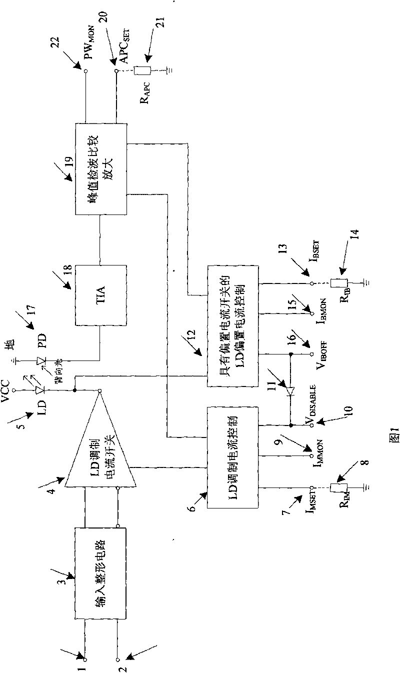
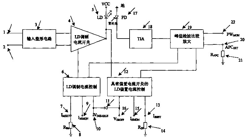
[0036] Please refer to figure 1 , the burst signal laser diode driver for optical communication transmitter provided by the present invention includes two differential signal input terminals 1 and 2, an input shaping circuit 3, a modulation current switch 4, a laser diode LD5, a laser diode modulation Current control circuit 6, a laser diode modulation current setting terminal I MSET 7. A laser diode modulation current setting resistor R IM 8. A laser diode modulation current monitoring terminal I MMON 9. A laser diode drive current cut-off voltage V DISABLE Input terminal 10, a unidirectional isolation diode 11, a laser diode bias current control circuit 12 with a bias current switch, a laser diode bias current setting terminal I BSET 13. A laser diode bias current setting resistor 14. A laser diode bias current monitoring terminal I BM...


PUM


Abstract

The invention discloses a laser diode driver for an optical communication transmitter. The laser diode driver comprises an input shaping circuit, a laser diode modulated current control circuit which is provided with a modulated current switch and is connected with the output end of the input shaping circuit and a to-be-driven laser diode, a laser diode bias current control circuit which is provided with a bias current switch and is connected with the laser diode, a photoelectric switching circuit, a peak detection circuit in direct-current coupling with the photoelectric switching circuit to carry out quick detection of electric signals output by the photoelectric switching circuit to output a detection signal and a differential comparison amplifying circuit in direct-current coupling with the peak detection circuit, wherein the output end of the differential comparison amplifying circuit is connected with the laser diode modulated current control circuit and the laser diode bias current control circuit to form a negative feedback loop. The laser diode driver has the advantages that the driver is suitable for transmitting both burst signals and random balanced signal flows.

Description

technical field [0001] The invention relates to the field of optical communication, in particular to a laser diode driver used in an optical communication transmitter. Background technique [0002] The role of laser diode drivers used in optical communication transmitters in optical communication systems is to convert transmitted voltage signals into optical signals. Usually it consists of a laser diode drive circuit, a laser diode (LD) and an automatic power control circuit. Wherein, the laser diode driving circuit converts the transmitted voltage signal into a corresponding current signal, and the current signal drives the laser diode, and the laser diode converts the driving current signal into an optical signal for output. Because the current / optical power conversion efficiency of each laser diode is different, and the conversion efficiency will not only increase with the change of ambient temperature, but also change with the aging of the laser diode (that is, with tim...

Claims


Application Information

Patent Timeline
Patent Type & Authority Applications(China)
IPC IPC(8): H01S5/042H01S5/0683
Inventor 易河清潘素敏刘尚新
Owner 上海博为光电科技有限公司
Why Eureka
Try Eureka