
Turning clamp

A fixture and turning technology, which is applied in turning equipment, turning equipment, clamping, etc., can solve the problems of low work efficiency, unstable clamping, and low coaxiality accuracy of two holes, etc. high efficiency effect

Inactive Publication Date: 2010-04-14
泉州泉风电机有限公司
View PDF1 Cites 8 Cited by
  • Summary
  • Abstract
  • Description
  • Claims
  • Application Information

AI Technical Summary

Problems solved by technology

[0004] The invention provides a turning fixture, which is applied to a lathe and can only be turned around and clamped to process workpieces with inner holes at both ends, especially for the finishing of the two-axis holes of a cage rotor. The fixture is not stable after clamping, the coaxiality accuracy of the two holes after processing is low, and the work efficiency of clamping the workpiece is low.

Method used


Image

  • Turning clamp
  • Turning clamp
  • Turning clamp

Examples


Embodiment Construction

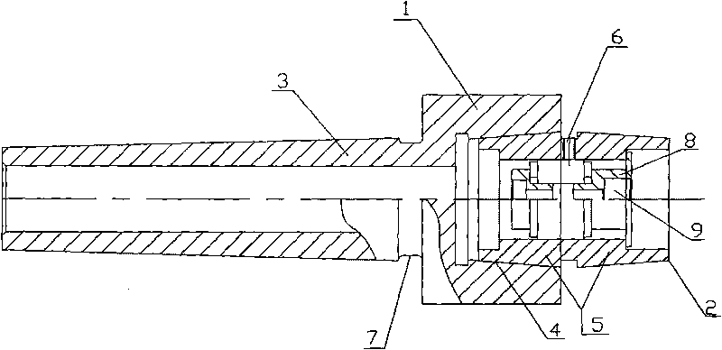
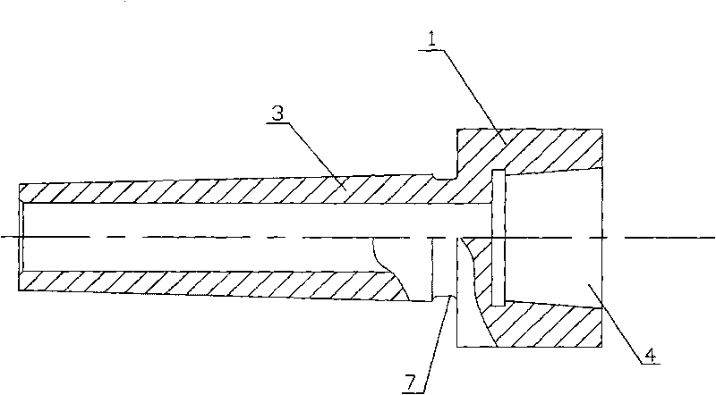
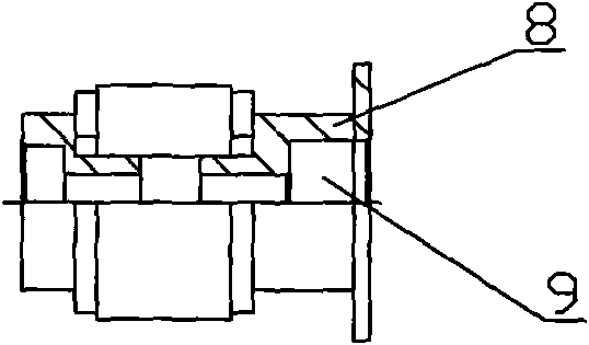
[0013] refer to figure 1 , a turning fixture, comprising a fixture main body 1, which also includes a fixture accessory 2, one end of the fixture main body 1 is a Morse taper shank 3 matched with the inner taper hole of the lathe spindle, and the other end is provided with an inner taper hole 4; The left and right parts of the fixture accessory 2 are symmetrically arranged as a tapered sleeve body 5, the outside of the tapered sleeve body 5 is closely matched with the inner tapered hole 4 of the fixture main body 1, and the inside of the tapered sleeve body 5 is in contact with the workpiece to be processed. The outer tapered surfaces 10 of 8 are in close contact with each other, and a screw hole 6 is provided in the middle of the two tapered sleeves 5 along the axial direction. When in use, the clamp attachment 2 and the processed workpiece 8 are fixedly connected through the screw holes 6 by screws. When processing the workpiece 8, the inner taper hole 4 of the lathe spindl...


PUM


Abstract

The invention discloses a turning clamp which comprises a clamp main body, wherein a Morse taper shank which is matched with a taper hole in a lathe spindle is arranged at one end of the clamp main body, and an inner taper hole is arranged at the other end of the clamp main body; the clamp also comprises a clamp accessory, wherein hollow tapered sleeve bodies are axisymmetrically arranged at a left part and a right part of the clamp accessory; the outer surface of each tapered sleeve body is in tapered-surface matching with the inner taper hole of the clamp main body, and the inner surface of each tapered sleeve body is in tapered-surface jointing with the outer tapered surface of a workpiece to be processed; a screw hole is arranged between the two tapered sleeve bodies of the clamp accessory along an axial line; and the inner taper hole of the lathe main body, the clamp main body and the clamp accessory are coincident along an axial line under a combined state. By using the turning clamp, the loading efficiency of the workpiece is high, and the whole body of the workpiece to be processed is tightly jointed with the whole body of the clamp, therefore, the workpiece is not easy to loosen and deviate from the spindle in the processing; and when the other end of the workpiece is processed after an inner hole at one end of the workpiece is processed, the distance between the axial lines of the inner holes at two ends can be effectively ensured to be less than 0.01mm, therefore, the processed workpiece accords with the coaxial precision requirement.

Description

technical field [0001] The invention relates to a turning jig, in particular to a turning jig which is applied to a lathe and can only be turned around and clamped to process the inner holes at both ends and has high coaxiality accuracy. Finishing to make it meet the coaxiality requirements. Background technique [0002] In the machining process, usually, the process of turning the other end of the part is completed by using the three-jaw chuck of the lathe itself. After one end of the machined part is turned, the machined part is removed and the The three jaws of the three-jaw chuck are changed from the front mounting mode to the reverse mounting mode, and then the three jaws of the chuck are supported from the inner hole of the processed part to realize positioning. The coaxiality accuracy of the inner holes at both ends of the above method is relatively low, and repeated manual clamping is required in actual operation, so the efficiency is also relatively low. [0003] ...

Claims


Application Information

Patent Timeline
IPC IPC(8): B23Q3/12B23B5/00
Inventor 蔡子章
Owner 泉州泉风电机有限公司
Learn More