Ironmaking technical furnace top charging technology

A furnace top charging and process technology, applied in the direction of fluidized bed furnace, etc., can solve the problems of inconvenient construction, high overall height of equipment, heat loss of sponge iron, etc., and achieve the effects of reducing energy consumption, increasing productivity, and reducing heat loss

Active Publication Date: 2010-04-14
CISDI ENG CO LTD
View PDF0 Cites 14 Cited by
  • Summary
  • Abstract
  • Description
  • Claims
  • Application Information

AI Technical Summary

Problems solved by technology

The existing method is that the reduction furnace and the melting furnace are arranged vertically in sequence. This method causes the overall height of the entire equipment to be too high, and the construction is inconvenient. At the same time, the sponge iron from the direct reduction furnace cannot be transported to the melting furnace quickly. , resulting in heat loss from the sponge iron

Method used


Image

  • Ironmaking technical furnace top charging technology
  • Ironmaking technical furnace top charging technology
  • Ironmaking technical furnace top charging technology

Examples


Embodiment 1

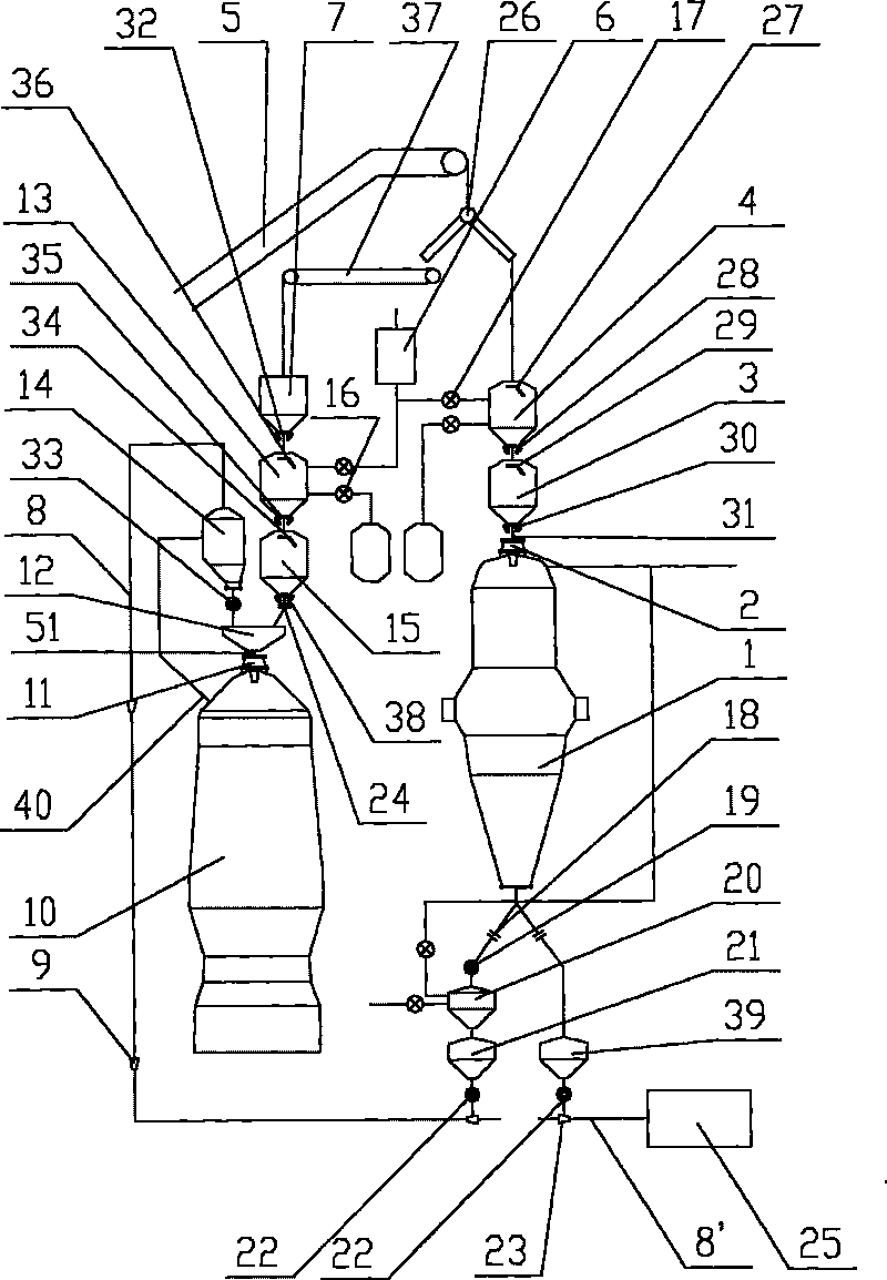
[0033] Embodiment 1: as figure 1 , the raw materials, fuel and auxiliary materials are transported to the top of the direct reduction furnace 1 and the melting furnace 10 through a belt conveyor 5 in batches, and the raw materials are sent to the top charging system of the direct reduction furnace 1 through a swing chute 26, The fuel and auxiliary materials are fed into the top charging system of melting furnace 10 .

[0034] The top charging system of direct reduction furnace 1 consists of pressure equalization bin 4, middle bin 3, equal pressure discharge system 17, upper sealing valve 27, lower sealing valve 29, material gate 28, material flow regulating valve 30, and corrugated compensator 31. Distributor 2 is composed. After the pressure equalization chamber is exhausted, open the upper sealing valve 27, the raw material enters the pressure equalization chamber 4, close the upper sealing valve 27, fill in nitrogen for pressure equalization, and after the pressure is cons...

Embodiment 2

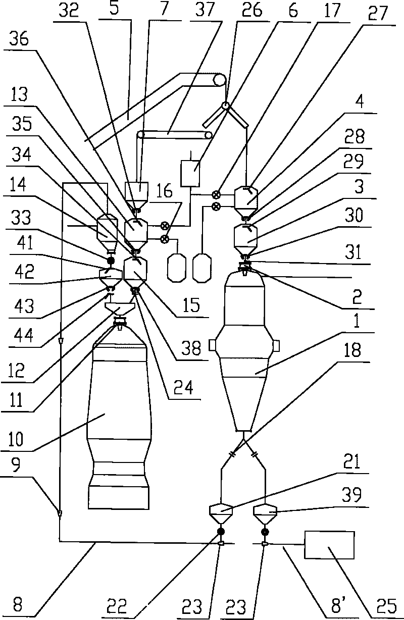
[0044] Embodiment 2: as figure 2 , The charging of raw material, fuel and auxiliary material of this embodiment is consistent with embodiment 1 scheme, and its difference is the delivery of hot state sponge iron.

[0045] The output of the hot sponge iron from the reduction shaft furnace 1 is sent to other process flow 25 in one way, and to the material gas separator 14 on the top of the melting furnace 10 in the other way. The pressure at other process flow 25 and the furnace top material gas separator 14 of melting furnace 10 is all less than the pressure in the reduction shaft furnace 1, therefore, the sponge iron enters the sending chamber 39 through the shut-off valve 18, enters the nozzle 23 through the rotary valve 22, At the nozzle 23, the transport medium gas is transported to other process flows 25 and the top material gas separator 14 of the melting furnace 10 through the pipeline 8.

[0046] The pressure in the furnace top material gas separator 14 of the melting...

Embodiment 3

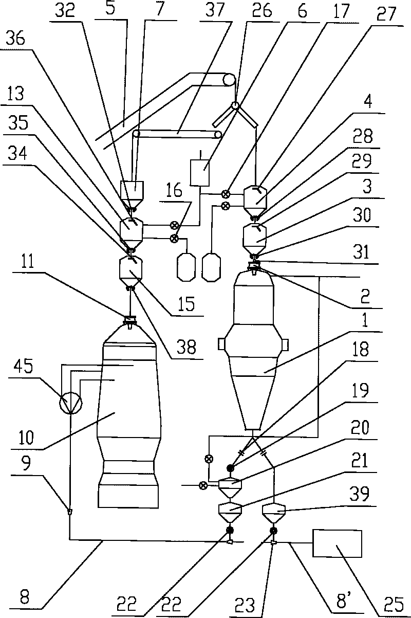
[0048] Embodiment 3: as image 3 , The charging of raw materials, fuels and auxiliary materials of this embodiment is consistent with the scheme shown in Example 1, the difference being the delivery of hot sponge iron.

[0049] This scheme saves the material gas separator 14 at the top of the melting furnace, and instead sends the sponge iron directly into the melting furnace 10 . After the hot sponge iron is discharged from the reduction shaft furnace 1, its delivery method is the same as figure 1 The scheme shown sends the sponge iron to the melting furnace top material gas separator 14, and after the sponge iron is transported to the distributor 45 through the pipeline 8, the sponge iron is distributed uniformly from the outlet of the melting furnace 10 in several pipelines. into the melting furnace.


PUM


Abstract

The invention relates to an ironmaking technical furnace top charging technology. The technology includes a direct reduction furnace top charging system, a melting furnace top charging system and a sponge iron delivery system, wherein the direct reduction furnace top charging system and the melting furnace top charging system are arranged in parallel, the top of a direct reduction furnace is provided with a raw material delivery device that delivers ores, fuels and auxiliary materials to the top of a direct reduction furnace (1) and a melting furnace (10); and after passing through at least one distribution device, the ores pass through the direct reduction furnace top charging system and are added in the direct reduction furnace (1), and the fuels and the auxiliary materials pass through the melting furnace top charging system and are then added in the melting furnace (10). The technology lowers the whole height of charging systems and is convenient for construction. Simultaneously, the method combines the technology of producing sponge iron through direct reduction with the technology of producing molten iron through melting into a whole, thus reducing the heat loss of thermal-state sponge iron in delivery process, improving productivity and decreasing energy consumption.

Description

technical field [0001] The invention relates to a furnace top charging process in an ironmaking process. Background technique [0002] Non-blast furnace ironmaking technology, as a new environmentally friendly ironmaking process, is widely promoted around the world. Raw materials pass through the direct reduction furnace to generate sponge iron, and the sponge iron passes through the conveying device and briquettes and then enters the melting furnace to generate molten iron. The existing method is that the reduction furnace and the melting furnace are arranged vertically in sequence. This method causes the overall height of the entire equipment to be too high, and the construction is inconvenient. At the same time, the sponge iron from the direct reduction furnace cannot be transported to the melting furnace quickly. , resulting in heat loss from the sponge iron. Contents of the invention [0003] The object of the present invention is to provide a furnace top charging p...

Claims


Application Information

Patent Timeline
Patent Type & Authority Applications(China)
IPC IPC(8): C21B13/00
Inventor 王涛蔡松伯王怀淳彭华国赵渭康曹伟宋华金明芳
Owner CISDI ENG CO LTD
Why Eureka
Try Eureka