Novel self-potential riding wheel supporting device of rotary cement kiln

A cement rotary kiln and supporting device technology, applied in rotary drum furnaces, furnace types, furnaces, etc., can solve the problems of heavy maintenance work, affecting the service life of tire belts and supporting rollers, complex structure, etc., to eliminate the phenomenon of deflection , The effect of eliminating the hollow phenomenon and the effective axial force

Active Publication Date: 2010-04-14
中材(天津)重型机械有限公司 +1
View PDF0 Cites 2 Cited by
  • Summary
  • Abstract
  • Description
  • Claims
  • Application Information

AI Technical Summary

Problems solved by technology

[0002] The supporting roller support device applied to the rotary kiln in the cement plant has extremely uneven stress caused by the foundation sinking of the multi-fulcrum rotary kiln, the installation error of the kiln shell, and the adjustment error of the supporting roller. Edge contact occurs, even for a two-stage support kiln with little change in the support reaction force, due to the bending deformation of the kiln shell, there will be edge contact between the tire belt and the supporting roller, which makes the contact between the tire belt and the supporting roller uneven, and the tire belt The local contact stress with the support roller is too large, which greatly affects the service life of the tire belt and the support roller, so it is necessary to use a self-aligning support roller support device
At present, the famous cement machinery design companies in the world have successively launched pneumatic, hydraulic and rubber block self-aligning roller support devices. The structure of the pneumatic and hydraulic self-aligning roller support devices is complex, and the maintenance workload is large. The effect is not satisfactory under the conditions, and the elastic rubber block of the bridge support is used to replace the cylinder and hydraulic cylinder, which can greatly simplify the structure of the support device and improve the reliability of its use. However, some rubber blocks currently used are naturally The supporting device of the supporting wheel, the pin shaft in the upper middle of the structure adopts rigid connection, which limits the self-positioning of the structure to a certain extent, that is, it is difficult to ensure the linear contact between the supporting wheel and the belt when the belt is skewed

Method used


Image

  • Novel self-potential riding wheel supporting device of rotary cement kiln
  • Novel self-potential riding wheel supporting device of rotary cement kiln
  • Novel self-potential riding wheel supporting device of rotary cement kiln

Examples


Embodiment Construction

[0019] In order to further understand the invention content, characteristics and effects of the present invention, the following examples are given, and detailed descriptions are as follows in conjunction with the accompanying drawings:

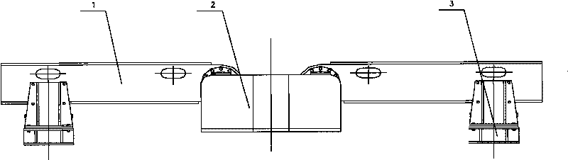
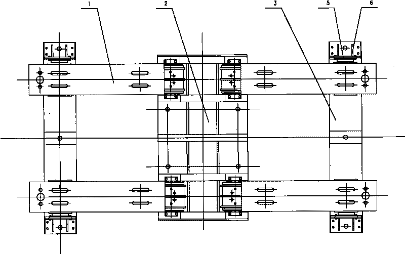
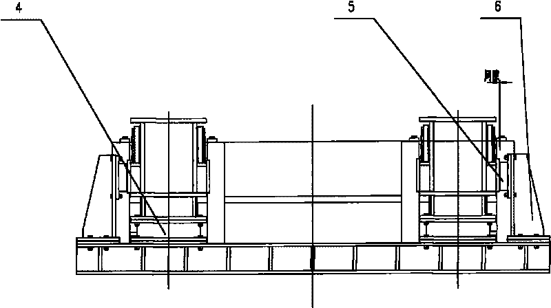
[0020] see figure 1 figure 2, image 3 , Figure 4 , Figure 5 and Image 6 , the four movable supports 1 are symmetrically arranged, one end of each movable support 1 is connected to the base 2 through the square body at both ends of the shaft 7, and the other end is supported on the radial elastic block 4, and the radial elastic block 4 is placed on the rubber On the seat 3, the head of the movable support 8 on the movable support 1 and the shaft 7 are connected by two thrust joint bearings 9 and one centripetal joint bearing 10, and the spherical centers of the three joint bearings all fall on the shaft 7. At the intersection of the transverse and longitudinal centerlines, the movable support 8 on the movable support 1 can do yaw movem...


PUM


Abstract

The invention relates to a novel self-potential riding wheel supporting device of a rotary cement kiln, which is formed by connecting a shifting bearing, a base, a rubber base, a radial elastic block and a sidewise elastic block. The novel self-potential riding wheel supporting device is characterized in that the shifting bearing consists of a movable support and a shaft arranged at the head of the movable support and linked with a plain redial bearing by two thrust articulated bearings; and sphere centers of the three bearings are coincided with the intersection point of a horizontal center line and a vertical center line of the shaft, and the inner cylindrical surface of the three bearings and the shaft form a hinged structure; both ends of the shaft are in square structures, one end of the shifting bearing is connected to the base by the square structures at the two ends of the shaft, and the other end is supported on the radical elastic block arranged on the rubber base. The invention has the advantages of simple structure, reliable use, convenient maintenance and long service life.

Description

technical field [0001] The invention belongs to the field of clinker calcining in the cement industry, and in particular relates to a novel self-positioning roller support device for a cement rotary kiln. Background technique [0002] The supporting roller support device applied to the rotary kiln in the cement plant has extremely uneven stress caused by the foundation sinking of the multi-fulcrum rotary kiln, the installation error of the kiln shell, and the adjustment error of the supporting roller. Edge contact occurs, even for a two-stage support kiln with little change in the support reaction force, due to the bending deformation of the kiln shell, there will be edge contact between the tire belt and the supporting roller, which makes the contact between the tire belt and the supporting roller uneven, and the tire belt The local contact stress with the support roller is too large, which greatly affects the service life of the tire belt and the support roller, so it is n...

Claims


Application Information

Patent Timeline
Patent Type & Authority Applications(China)
IPC IPC(8): F27B7/22
Inventor 兰广林邓军庞英尤小平
Owner 中材(天津)重型机械有限公司
Why Eureka
Try Eureka