Parallel flow heat exchanger and wing band structure thereof

A technology of heat exchangers and fin strips, applied in the field of air conditioning, can solve problems such as poor drainage of condensed water and easy freezing

Active Publication Date: 2010-04-14
TIANJIN SANDEN AUTO AIR CONDITIONING
View PDF4 Cites 5 Cited by
  • Summary
  • Abstract
  • Description
  • Claims
  • Application Information

AI Technical Summary

Problems solved by technology

[0007] Due to the structure of the finned strips, the conventional technology can only be used as a condenser on a single cooler because the condensed water on the surface of the finned strips of the heat exchanger does not drain smoothly and is easy to freeze.

Method used


Image

  • Parallel flow heat exchanger and wing band structure thereof
  • Parallel flow heat exchanger and wing band structure thereof
  • Parallel flow heat exchanger and wing band structure thereof

Examples


Embodiment Construction

[0037] Below in conjunction with preferred embodiments, the specific implementation, features and effects provided by the present invention are described in detail as follows; for the purpose of simplicity and clarity, the description of known technologies is appropriately omitted below to avoid unnecessary details Affect the description of this technical solution.

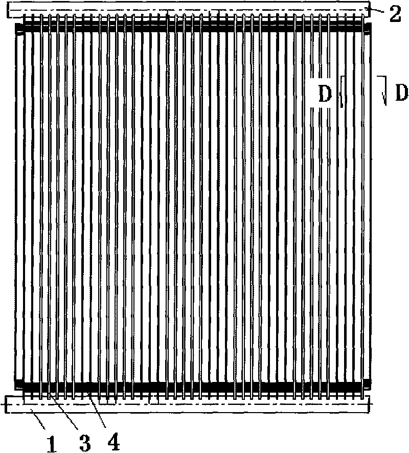
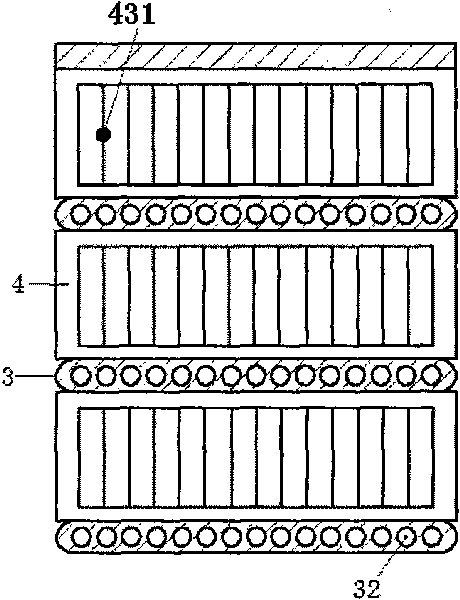
[0038] see Figure 1-6 As shown, a parallel flow heat exchanger and its fin structure, including a first header 1, a second header 2, and a flat heat exchanger installed between the two headers to allow refrigerant to pass through The tube 3 and the fin strip 4 installed between the flat heat exchange tubes, the fin strip is made into a corrugated structure with a crest section 41, a straight section section 43, and a wave trough section 42; each of the fin strips The straight sections are all provided with windows 4311 for ventilation, forming a louver section 431 structure, wherein,

[0039] The two ends of th...


PUM


Abstract

The invention discloses a parallel flow heat exchanger and a wing band structure thereof and relates to a wing band structure of a micro-channel heat exchanger in the filed of air conditionings. The structure of a blindwindow region part formed by a window is arranged at the straight section part of the wing band, and the window enables air to flow downwards along the window slantwise in the flow direction of the air. In the heat exchanger, plat heat exchange tubes which allow refrigerant to pass are arranged between two liquid collection tubes; and a wing band device is arranged among the flat heat exchange tubes. The wing band structure is reasonable, and the window of the blindwindow region part is artfully configured into a structure which enables air to flow downwards slantwise in the flow direction of the air, so that condensed water can be drained smoothly without icing, and heat exchange efficiency can be improved effectively. The reasonable arrangement of the structure of the window can achieve better heat exchange efficiency of the heat exchanger, and the heat exchanger used the invention can be best choice for the specific industry to be configured with heat pumps, evaporators and other air conditionings; and the invention can be applied to all fields of air conditionings and has higher industrial promotion value.

Description

technical field [0001] The invention belongs to the field of air conditioners, relates to a fin strip structure of a fine channel heat exchanger, and is suitable for household air conditioners, commercial air conditioners and central air conditioners. Background technique [0002] The engineering background of microscale heat transfer problems comes from the cooling of high-density electronic devices in the 1980s and the flow and heat transfer problems in microelectromechanical systems that emerged in the 1990s. Its characteristic is that when the scales of space and time are miniaturized, many physical phenomena appear that are different from conventional scales. Micro-channel radiator is a technology that the industry has been researching and using. It is reported that as early as the 1980s, scientists proposed the concept of "micro-channel radiator". With the advancement of technology, micro-channels are used for heat exchange in household air conditioners. Devices are s...

Claims


Application Information

Patent Timeline
Patent Type & Authority Applications(China)
IPC IPC(8): F28F3/02F25B39/02F25B39/04
Inventor 陈启丁桂庆魏庆奇
Owner TIANJIN SANDEN AUTO AIR CONDITIONING
Why Eureka
Try Eureka