Flow passage structure design method for anti-clogging drip irrigation emitter

A technology for structural design and sprinklers, applied in botany equipment and methods, instruments, calculations, etc., can solve problems such as eliminating blockage, difficult operation, and unspecific judgment methods

Inactive Publication Date: 2010-04-14
NORTHWEST A & F UNIV
View PDF1 Cites 10 Cited by
  • Summary
  • Abstract
  • Description
  • Claims
  • Application Information

AI Technical Summary

Problems solved by technology

The above-mentioned methods provide very useful explorations for solving the clogging problem of emitters, but it is difficult to fundamentally eliminate the clogging problem, and the actual operation of the above-mentioned optimal design methods is relatively difficult, and some sacrifice The hydraulic performance of the emitter
In addition, the invention patent "An anti-clogging design method for drip irrigation emitter based on two-phase flow simulation" (ZL 200610018493.7) provides an anti-clogging design method based on two-phase flow simulation. The accumulation of solid particles is the judgment standard, mainly for the structure of the diamond-shaped bypass labyrinth flow channel; although the method provided by the invention patent provides a reference for anti-clogging design, the judgment method is not specific and the scope of application is small
In addition, in the design process of this invention patent, it mainly relies on numerical simulation methods, lacks verifiable visual observation and analysis methods, and it is difficult to guarantee the accuracy of the results

Method used


Image

  • Flow passage structure design method for anti-clogging drip irrigation emitter
  • Flow passage structure design method for anti-clogging drip irrigation emitter
  • Flow passage structure design method for anti-clogging drip irrigation emitter

Examples


Embodiment Construction

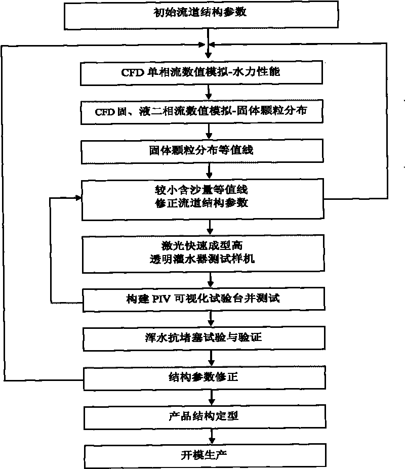
[0032] According to the technical solution of the present invention, an anti-clogging drip irrigation emitter flow channel structure design method specifically includes the following steps:

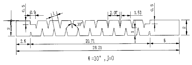
[0033] The first step is to determine the preliminary flow channel structure and parameters according to the design requirements. The flow channel structure is trapezoidal, rectangular or arc-toothed labyrinth structure. The width of the channel is between 0.6mm and 1.2mm, and the depth of the channel is 0.6mm. ~1.0mm, and according to the requirements of CFD numerical simulation software, select the following mathematical model

[0034] ∂ ∂ x k ( ρu k ∂ u ...


PUM

PropertyMeasurementUnit
Volumeaaaaaaaaaa

Abstract

The invention discloses a flow passage structure design method for an anti-clogging drip irrigation emitter. The method is based on computational fluid dynamics CFD and particle image velocimetry PIV, corrects flow passage structure parameters by means of combining CFD simulation, LRP test sample fast manufacturing and PIV visualized test, processes samples, performs a muddy water anti-clogging test according to relevant international standards, and finally realizes product structure setting and mode opening production. The method can remarkably improve anti-clogging property of the emitter. The method is adopted to perform quadratic optimization of a ladder-type flow passage structure of the drip irrigation emitter and standardize optimizing parameters, thereby normal irrigation days of the emitter are added to 11 days from 6 days before the optimization; maximum sand content is decreased to about 5 % from over 60 %; and anti-clogging property of the emitter is remarkably improved.

Description

technical field [0001] The invention relates to a flow channel structure design method of an anti-clogging drip irrigation emitter, belonging to the technical fields of water-saving irrigation, ecological construction and agricultural equipment manufacturing. Background technique [0002] Clogging has always been a key problem that plagues the development of drip irrigation technology. The life of the drip irrigation system is reduced due to clogging, the cost of use is increased, and the quality of irrigation is reduced. In addition to the water quality, the cause of the blockage is mainly due to the unreasonable flow channel structure. For this reason, it is of great significance to study the anti-clogging design of drip irrigation emitters to improve system life, save costs, and improve irrigation quality. [0003] In order to solve the above problems, predecessors also proposed many flow channel structure design methods, for example, applying the idea of ​​the main cha...

Claims


Application Information

Patent Timeline
IPC IPC(8): G06F17/50A01G25/02
CPCY02A40/22
Inventor 吴普特牛文全范兴科喻黎明
Owner NORTHWEST A & F UNIV
Why Eureka
Try Eureka