Slow cooker with touch control structure

A control structure and touch-type technology, which is applied in the direction of home appliances, kitchen utensils, and special materials for cooking utensils, etc., can solve the problems of reduced service life of appliances, low temperature control accuracy, fatigue in use, etc., and achieves convenient operation, clear hand feeling, The effect of easy operation

Inactive Publication Date: 2010-04-21
NINGBO WUJI ELECTRIC APPLIANCE
View PDF1 Cites 5 Cited by
  • Summary
  • Abstract
  • Description
  • Claims
  • Application Information

AI Technical Summary

Problems solved by technology

[0002] Slow cooker is also a kind of electric heating pot, and its function of general electric heating pot is limited to roasting or boiling, and the existing structure of slow cooker, as the patent No. is ZL200720192291.4 Chinese invention benefit document " slow cooker " ( The announcement number is CN201088460Y); including the shell, the upper chamber of the shell is buckled with an aluminum gall, the inner cavity of the aluminum pot is embedded with a unit pottery pot, the outer ring of the lower part of the aluminum pot is tightly sleeved with a heating ring, and the heating ring is electrically connected There is a thermostat that can control the temperature range; the bottom of the outer wall of the shell is fixed with a rocker switch with its own indicator light and electrically connected to the external power supply, and the rocker switch is also electrically connected to the thermostat; The rocker switch integrates indication and operation; the power supply of this design must be turned on and off by a rocker switch, and the power supply is frequently switched on and off. Due to the frequent operations, it is easy to cause fatigue in use, that is, the entire appliance is reduced. The service life; the dual structure of the rocker switch and the thermostat is configured, the structure is complex, and the temperature control accuracy is also low

Method used


Image

  • Slow cooker with touch control structure
  • Slow cooker with touch control structure
  • Slow cooker with touch control structure

Examples


Embodiment Construction

[0021] The present invention will be further described in detail below in conjunction with the accompanying drawings and embodiments.

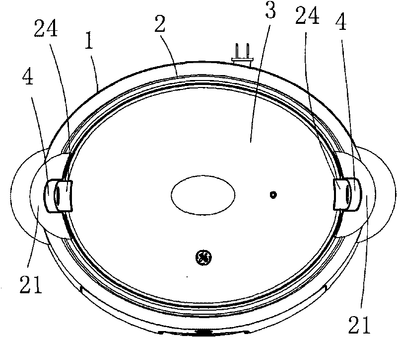
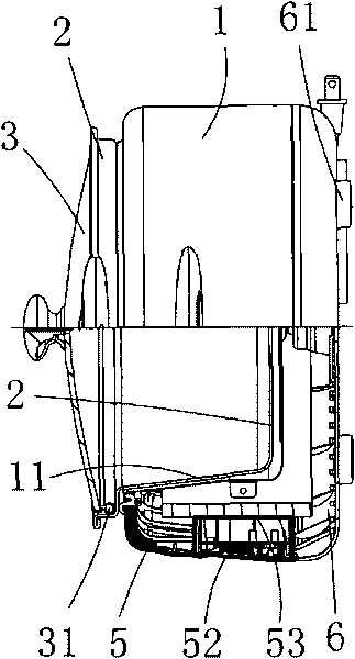
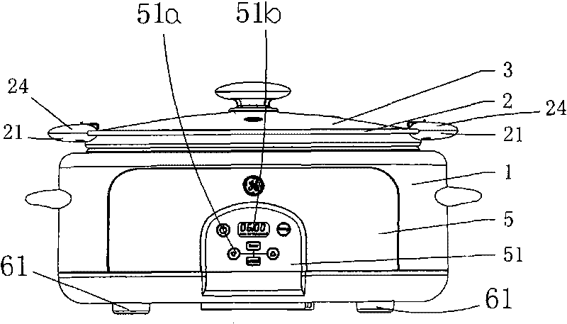
[0022] Such as Figure 1 to Figure 6 As shown, the icon numbers are explained as follows: pot body 1, heating pot 11, boss 11a, heating ring 12, insulation cotton 13, working pot 2, pot handle lower cover 21, spring 22, steel ball 23, pot handle upper cover 24, Pot cover 3, sealing ring 31, lock 4, decorative sheet 5, control panel 51, control button symbol 51a, transparent window 51b, PCB board 52, board cover 53, lower cover 6, support strap 61.

[0023] In the embodiment of the present invention, the slow cooker with a touch control structure includes a pot body 1 with a heating pot 11 in the middle, a working pot 2 embedded in the middle cavity of the heating pot 11, and a cover on the upper part of the working pot 2 There is a pot cover 3, and the upper edge of the working pot 2 is symmetrically fixed on both sides of the bottom surface ...


PUM


Abstract

The invention discloses a slow cooker with a touch control structure, comprising a cooker body provided with a heating cooker in the middle. A working cooker is embedded into an inner cavity in the middle of the heating cooker and a cooker cover is arranged on the upper part of the working cooker; coking handle lower covers are symmetrically arranged on the upper side of the working cooker along two sides of the bottom surface; the inner sides of the middle parts of the cooker handle lower covers are respectively provided with one spring hole, and springs and steel beads are embedded into the spring holes; cooker handle upper covers are arranged on the upper part of the cooker handle lower cover, and lock catches are slidably arranged between the cooker handle upper covers and the cooker handle lower covers; the bottom surfaces of the lock catches are supported against and slidably matched with the steel beads, and the steel beads control the limitation of the sliding position of the lock catches; a sealing ring which is made of silica gel and has a closed loop structure is fixed on the periphery of the cooker cover along the lower part and controls the sealing connection between the cooker cover and the working cooker; a lock catch self-lock structure with simple structure and convenient operation is additionally arranged between the working cooker and the cooker cover; and a left hand plate and a right hand plate of a cooker body are inlayed into a plastic structure by screws, and the cooker body has an appearance designed according to the ergonomics, is firm and durable, not easy to fall off and cannot scald hands.

Description

technical field [0001] The invention relates to the technical field of electric heating pots, in particular to a slow cooker with a touch control structure. Background technique [0002] Slow cooker is also a kind of electric heating pot, and its function of general electric heating pot is limited to roasting or boiling, and the existing structure of slow cooker, as the patent No. is ZL200720192291.4 Chinese invention benefit document " slow cooker " ( The announcement number is CN201088460Y); including the shell, the upper chamber of the shell is buckled with an aluminum gall, the inner cavity of the aluminum pot is embedded with a unit pottery pot, the outer ring of the lower part of the aluminum pot is tightly sleeved with a heating ring, and the heating ring is electrically connected There is a thermostat that can control the temperature range; the bottom of the outer wall of the shell is fixed with a rocker switch with its own indicator light and electrically connected ...

Claims


Application Information

Patent Timeline
Patent Type & Authority Applications(China)
IPC IPC(8): A47J27/00A47J36/04A47J36/10
Inventor 施军达张华平
Owner NINGBO WUJI ELECTRIC APPLIANCE
Why Eureka
Try Eureka