Device for cushioning automobile crash by tires
A technology for tires and automobiles, which is applied in the field of tire buffering devices for automobile collisions, can solve the problems of lack of collision safety protection devices, flattening of the cab, and life-threatening threats to drivers and passengers, so as to improve personal safety, increase safety, and improve social safety. Benefit and significant effect
- Summary
- Abstract
- Description
- Claims
- Application Information
AI Technical Summary
Problems solved by technology
Method used
Image
Examples
Embodiment 1
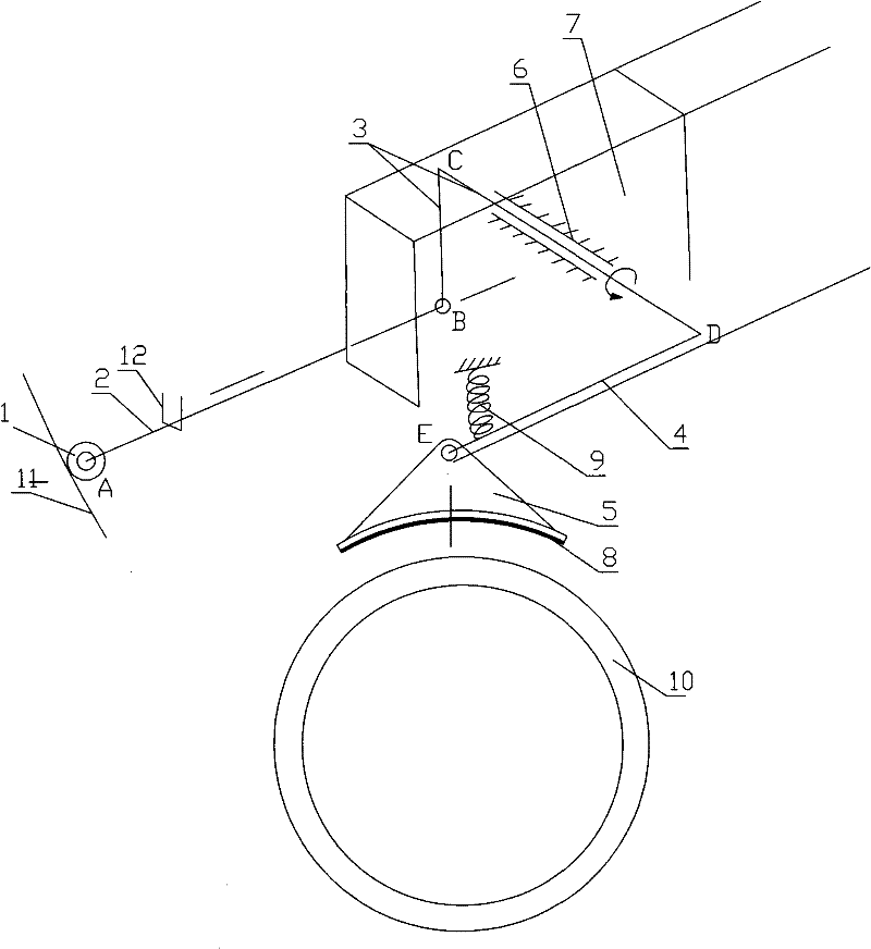
[0029] Specific examples of the present invention are attached figure 1As shown, including bumper 11, longitudinal beam 7 and tire 10, it is characterized in that: described longitudinal beam 7 is provided with a support sleeve 6, and " L " type swing bar 3 is housed in support sleeve 6, and its one end is connected with The push rod 2 is hinged, and the push rod 2 is connected with the positioning wheel 1 through the crane plant 12 fixed on the vehicle body, and the positioning wheel 1 is freely connected with the front bumper 11 of the vehicle; The splines are vertically connected, the ratio of the pressure rod 4 to the vertical rod B-C section of the "L" type swing rod 3 is 1 to 2, the pressure rod 4 is hung on the vehicle body through the spring 9, and is hinged with the pressure block 5, and the pressure is ensured. The centerline of the block 5 coincides with the circumferential centerline of the tread; the pressure block 5 is triangular, and the lower part is concave ar...
Embodiment 2
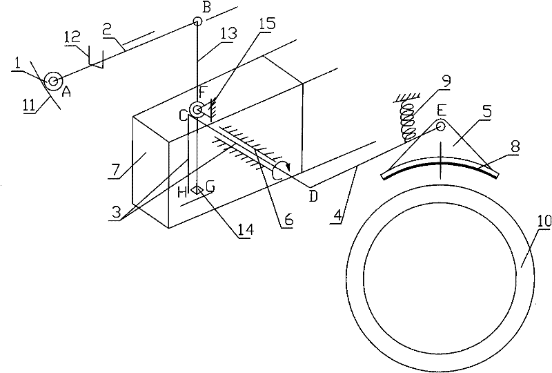
[0031] Specific examples of the present invention are attached figure 2 As shown, including bumper 11, longitudinal beam 7 and tire 10, it is characterized in that: described longitudinal beam 7 is processed with supporting point 15, and the middle part of straight swing bar 13 is hinged with supporting point 13, and its upper end is connected with push rod 2 The push rod 2 is connected with the positioning wheel 1 through the spider 12 fixed on the car body, and the positioning wheel 1 is freely connected with the front bumper 11 of the vehicle; there is a small baffle plate 14 at the lower end of the straight swing rod 13, and is mounted on the longitudinal The lower end of the "L"-shaped pendulum 3 in the supporting sleeve 6 on the beam 7 is freely connected; The ratio of the B-C section of the vertical bar of the bar 3 is 1 to 2, and the pressing bar 4 is hung on the vehicle body through the spring 9, and is hinged with the pressing block 5, and ensures that the center li...
Embodiment 3
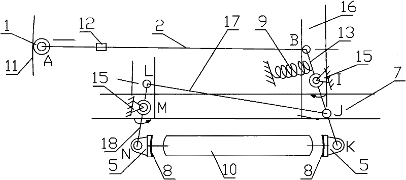
[0033] Specific examples of the present invention are attached image 3 As shown, it includes a bumper 11, a longitudinal beam 7, a beam 16 and a tire 10; it is characterized in that the beam 16 is processed with a support point 15; the middle part of the straight swing link 13 is hinged with the support point 15, and the straight swing link 13 One end of the push rod 2 is hinged; the push rod 2 is connected with the positioning wheel 1 through the spider 12 fixed on the car body, and the positioning wheel 1 is freely connected with the front bumper 11 of the vehicle; Spring 9 is connected with car body, and its other end is hinged with briquetting block 5; One end of middle push rod 17 is hinged at the middle part of the I-K section of straight swing link 13, and the other end is hinged with an end of corresponding swing link 18; The swing rod 18 is hinged with the support point 15 mounted on the longitudinal beam 7, and the other end is hinged with the pressure block 5; the ...
PUM
 Abstract
Description
Claims
Application Information
 - R&D
- Intellectual Property
- Life Sciences
- Materials
- Tech Scout
- Unparalleled Data Quality
- Higher Quality Content
- 60% Fewer Hallucinations
Browse by: Latest US Patents, China's latest patents, Technical Efficacy Thesaurus, Application Domain, Technology Topic, Popular Technical Reports.
© 2025 PatSnap. All rights reserved.Legal|Privacy policy|Modern Slavery Act Transparency Statement|Sitemap|About US| Contact US: help@patsnap.com


