
Low-temperature heat energy recovering apparatus of heat and electricity co-generation and recovering method thereof

A technology of combined heat and power generation and heat recovery, applied in the energy field, can solve problems such as waste of water resources, achieve the effects of increasing power generation, reducing irreversible heat transfer losses, and reducing heat loss

Active Publication Date: 2012-09-19
联合优发生物质能源徐州有限公司
View PDF0 Cites 0 Cited by
  • Summary
  • Abstract
  • Description
  • Claims
  • Application Information

AI Technical Summary

Problems solved by technology

Its water consumption can reach more than 60% of the water consumption of the whole plant, resulting in a great waste of water resources

Method used

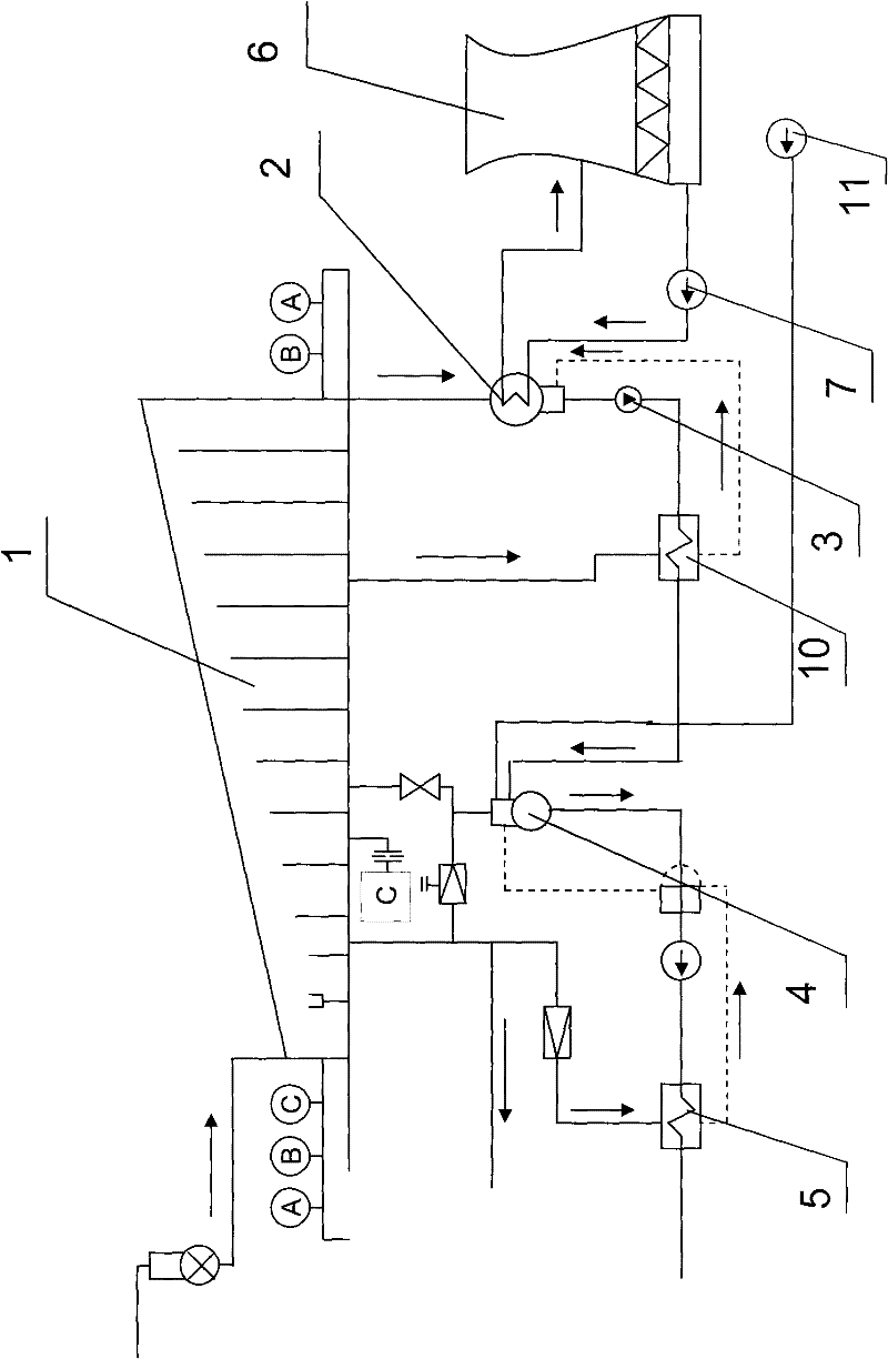

Image

  • Low-temperature heat energy recovering apparatus of heat and electricity co-generation and recovering method thereof
  • Low-temperature heat energy recovering apparatus of heat and electricity co-generation and recovering method thereof
  • Low-temperature heat energy recovering apparatus of heat and electricity co-generation and recovering method thereof

Examples


Embodiment 1

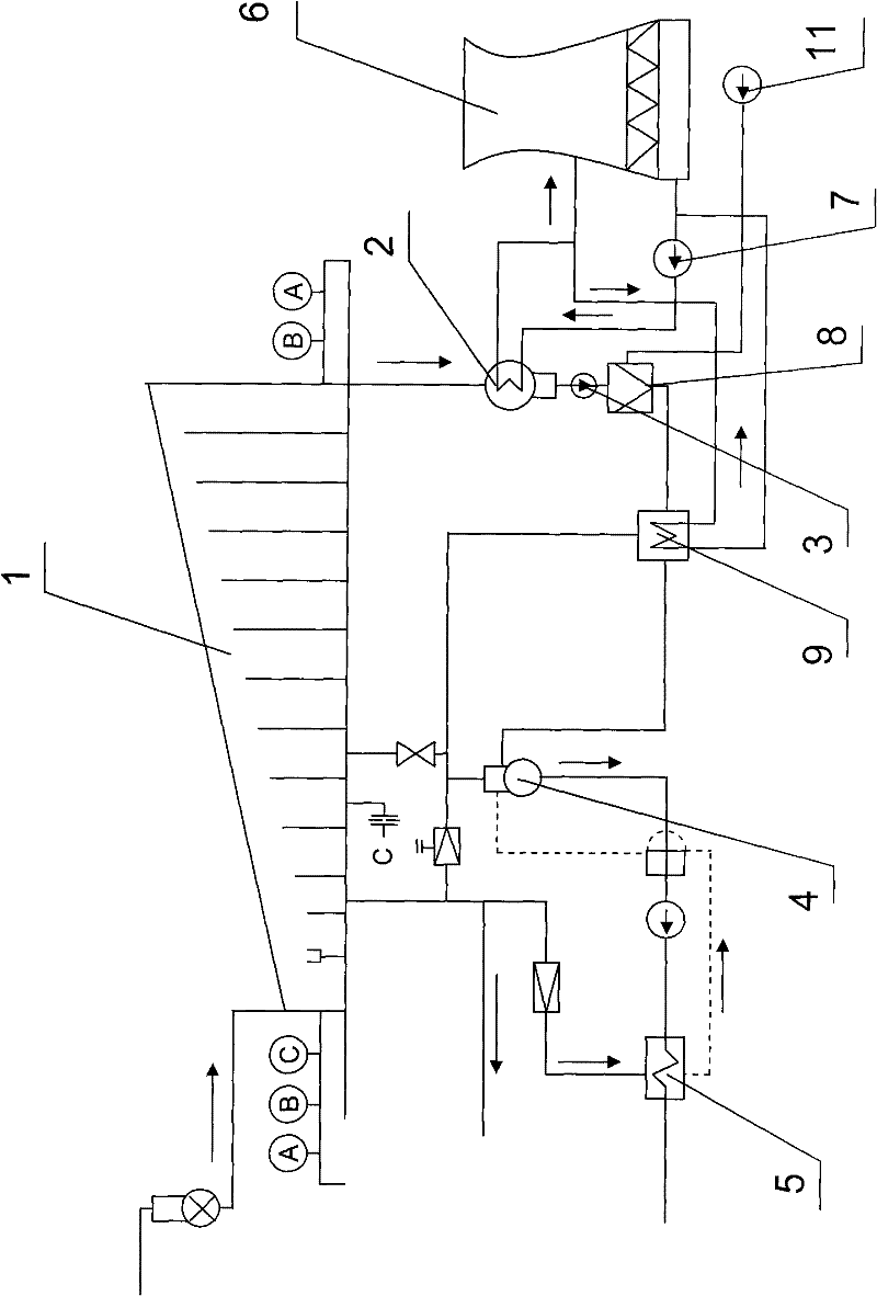
[0051] Such as figure 2 As shown, the cogeneration low-temperature heat energy recovery device includes a steam boiler, a steam turbine 1, a generator, a condenser 2, a condensate pump 3, a deaerator 4, a high-pressure heater 5, a cooling tower 6, and a demineralized water pump 11. The steam turbine 1 is connected to the condenser 2 through an exhaust cylinder, and the condenser 2 is connected to the cooling tower 6 through pipelines to form a large water circuit; the device also includes:

[0052] Water replenishment mixer 8, the water inlet of the water replenishment mixer is connected to the condenser through the condensate pump, and the water inlet of the water replenishment mixer is also connected to the water outlet of the desalinated water pump through a pipeline, so The water outlet of the water replenishing mixer is connected with the water inlet of the feed water heater through a pipeline;

[0053] A feedwater heater 9, the water inlet of the feedwater heater is co...

Embodiment 2

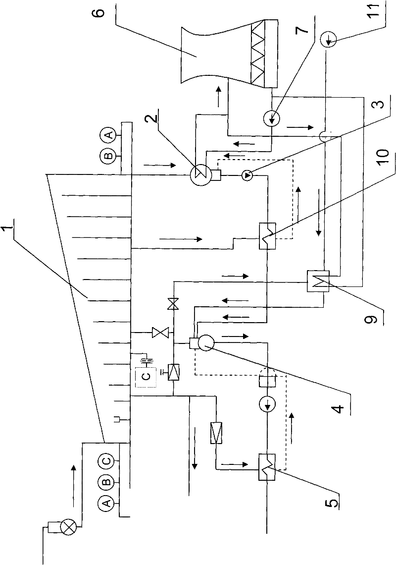
[0080] The difference from Example 1 is that the demineralized water is sent to the feed water heater for heating, and the condensed water is sent to the low-pressure heater for heating.

[0081] Such as image 3 As shown, the cogeneration low-temperature heat energy recovery device includes a steam boiler, a steam turbine 1, a generator, a condenser 2, a condensate pump 3, a low-pressure heater 10, a deaerator 4, a high-pressure heater 5, a cooling tower 6 and a desalination Water pump 11, the steam turbine 1 is connected to the condenser 2 through the exhaust cylinder, and the condenser 2 is connected to the cooling tower 6 through pipelines to form a large water circuit; the water inlet of the low-pressure heater 10 passes through The condensed water pump 3 is connected with the condenser 2, the water outlet of the low-pressure heater 10 is connected with the water inlet of the deaerator 4 through a pipeline, and the steam inlet of the low-pressure heater 10 is connected wi...


PUM


Abstract

The invention relates to a low-temperature heat energy recovering apparatus of heat and electricity co-generation and a recovering method thereof. The apparatus comprises a steam boiler, a steam turbine, a generator, a condenser, a deaerator, a high-pressure heater, a cooling tower and a demineralized water pump. The steam turbine is connected with the condenser through an exhaust cylinder. The condenser is connected with the cooling tower through pipelines to form a water channel large circulation. The device is characterized by also comprising a water supplementing mixer and a heat pump type feed water heater, wherein the water supplementing mixture is respectively connected with the condenser and the demineralized water pump through pipelines, the heat pump type feed water heater is respectively connected with the water supplementing mixer and the deaerator through the pipelines. The condenser and the feed water heater are connected with the cooling tower through pipelines to form water channel small circulation. The heat pump type feed water heater is driven by steam extracted by the steam turbine. The apparatus further comprises an automatic control apparatus. The invention can reduce the cold source loss and improve the comprehensive heat efficiency.

Description

technical field [0001] The invention belongs to the field of energy technology, and relates to a low-temperature heat recovery device for cogeneration of heat and power and a recovery method thereof. Background technique [0002] Combined heat and power refers to the superheated steam supplied by the steam boiler to the steam turbine generator. In the process of expansion and work in the steam turbine, it not only undertakes the two tasks of generating electricity but also providing steam to different users. Because part or all of it (referring to the back pressure turbogenerator unit) has worked steam, it is no longer discharged into the condenser, but is supplied to other heat users for utilization, thereby improving the efficiency of the thermal cycle. The purpose of combined heat and power is to reduce the loss of cold source. Even under the condition of maximum steam supply, there is still and must be a part of steam discharged to the condenser, and the latent heat of ...

Claims


Application Information

Patent Timeline
Patent Type & Authority Patents(China)
IPC IPC(8): F01K19/00F01K11/02F22D1/32F22D1/50
CPCY02P80/15
Inventor 刘锋向文国高迎旭田海江夏彦龙
Owner 联合优发生物质能源徐州有限公司
Learn More