Coal type less oil ignition burner capable of controlling vortex width

A micro-oil ignition and burner technology, which is applied to burners, burners for burning powder fuel, combustion methods, etc., can solve the problems of lack of adjustability, long heating time, and inability to ignite normally, and achieve extended residence time, The effect of improving ignition stability

Inactive Publication Date: 2010-04-21
CHINA JILIANG UNIV
View PDF1 Cites 10 Cited by
  • Summary
  • Abstract
  • Description
  • Claims
  • Application Information

AI Technical Summary

Problems solved by technology

Chinese patents ZL03255982.8, ZL200520145352.2 etc. have announced several different forms of micro-oil ignition burners, and these burners have their own advantages in realizing micro-oil ignition and low-load stable combustion; The method of arranging the oil gun on one side is adopted, so the heating of the pulverized coal is heated on one side; this results in a long heating time, requiring a longer size of the entire pulverized coal burner
Therefore, when the actual required length of the entire pulverized coal burner exceeds the upper limit, it will lead to a reduction in the burnout rate of pulverized coal at the outlet of the burner; this will greatly reduce the stability of ignition, and even lead to failure of normal ignition
ZL200710156019.5 uses multiple oil guns to solve the problem of single-sided heating, but its adaptability to coal types is still limited and lacks adjustability

Method used


Image

  • Coal type less oil ignition burner capable of controlling vortex width
  • Coal type less oil ignition burner capable of controlling vortex width
  • Coal type less oil ignition burner capable of controlling vortex width

Examples


Embodiment Construction

[0016] The present invention will be further described below in conjunction with the accompanying drawings and embodiments.

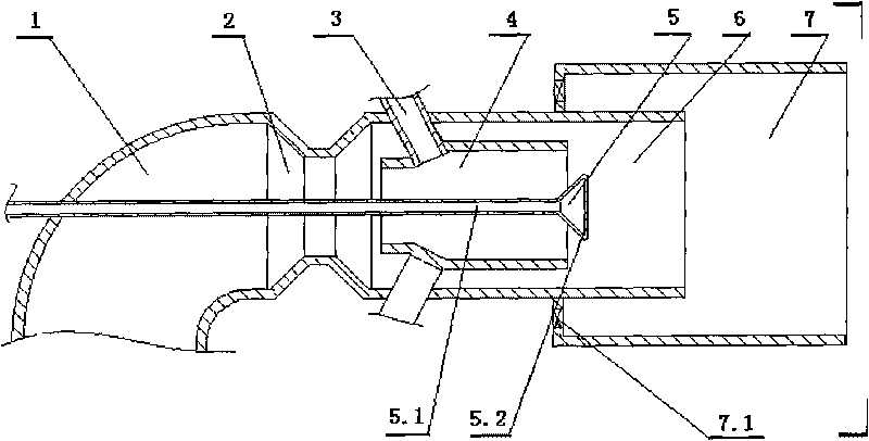
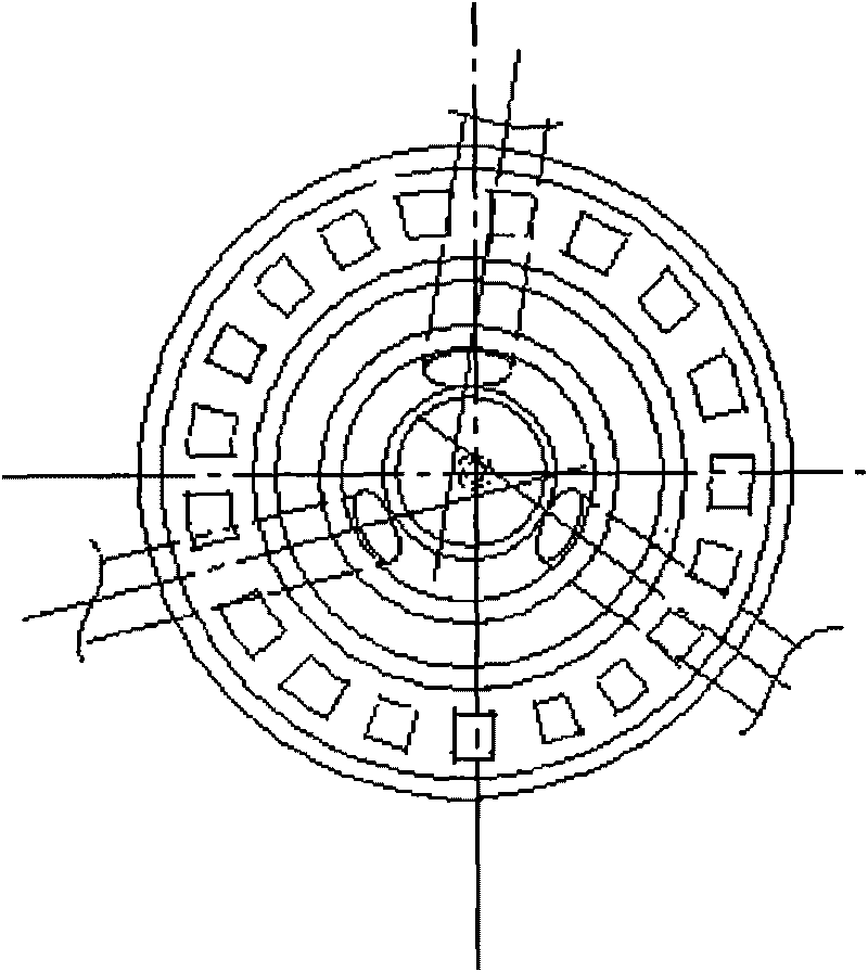
[0017] Such as figure 1 , figure 2 As shown, the present invention includes a primary air duct with a circular cross section and an elbow at one end coincident with the axes, a pulverized coal concentrator 2, a primary pulverized coal combustion chamber 4, a secondary pulverized coal combustion chamber 6 and a tertiary coal Pulverized coal combustion chamber 7; the pulverized coal concentrator 2 of the variable-diameter pipeline forming the throat of the primary air duct 1 communicates with the secondary pulverized coal combustion chamber 6, and the pulverized coal combustion chamber 4 of the primary pulverized coal is installed on the secondary pulverized coal combustion chamber. In the combustion chamber 6, the secondary pulverized coal combustion chamber 6 stretches into the tertiary pulverized coal combustion chamber 7, and the tertiary pulverized...


PUM


Abstract

The invention discloses a coal type less oil ignition burner capable of controlling the vortex width. A primary air pipeline of the coal type less oil ignition burner is communicated with a second-stage pulverized coal burning chamber through a pulverized coal condenser; a first-stage pulverized coal burning chamber is arranged in the second-stage pulverized coal burning chamber which extends into a third-stage pulverized coal burning chamber; and the lateral surface of the third-stage pulverized coal burning chamber connected with the second-stage pulverized coal burning chamber is equidistantly provided with a plurality of secondary air inlets. One end of a central air duct of a controllable vortex bluff body is a cavity cone; the central air duct passes through the primary air pipeline, the pulverized coal condenser and the first-stage pulverized coal burning chamber; the cavity cone extends out and is positioned outside the first-stage pulverized coal burning chamber; and the circumference at the bottom of the cavity cone is evenly provided with a plurality of round holes and a plurality of oil burning chambers obliquely and equidistantly pass through the second-stage pulverized coal burning chamber and then are arranged on the first-stage pulverized coal burning chamber. By adopting the controllable vortex bluff body, the invention prolongs the stay time of pulverized coal in the burners and improves the ignition stability. The invention is not only can be used as the ignition burner, but also can be used as a main burner and a burner with lower load and stable burning.

Description

technical field [0001] The invention relates to a pulverized coal burner, in particular to a coal micro-oil ignition burner with controllable swirl width. Background technique [0002] The conventional method for boiler start-up and low-load stable combustion in a thermal power station is to use a large oil gun to inject oil into the furnace and support combustion. Depending on the furnace type, 50-200 tons of fuel oil needs to be put in during the cold start of the boiler from ignition to pulverized coal feeding with load. With the use of micro-oil ignition and combustion-supporting technology, according to the principle of step-by-step energy amplification, a small amount of pulverized coal can be directly ignited with a high-energy oil gun, and then more pulverized coal can be ignited step by step; thus, a small amount of oil can be used to start the cold furnace of the boiler. According to different types of coal, the oil saving effect can generally reach 60-98%. At pr...

Claims


Application Information

Patent Timeline
Patent Type & Authority Applications(China)
IPC IPC(8): F23D1/00
Inventor 闫志勇吴阿塞海洋孙笑茹
Owner CHINA JILIANG UNIV
Why Eureka
Try Eureka