
Push-off mode adjustable cantilever of overhead contact line equipment of electrified railway

An electrified railway and catenary technology, applied in the field of wrist arm positioning device and anti-positioning adjustable wrist arm, can solve the problems affecting the contact suspension balance of the contact line and the load-bearing cable, etc.

Active Publication Date: 2012-12-05
SHAANXI FLYWHEEL HIGH SPEED RAIL EQUIP CO LTD
View PDF0 Cites 0 Cited by
  • Summary
  • Abstract
  • Description
  • Claims
  • Application Information

AI Technical Summary

Problems solved by technology

[0004] The purpose of the present invention is to provide a reverse positioning adjustable wrist-arm device for electrified railway catenary, which is an adjustable structure and stable in structure, and solves the problem that the existing wrist-arm positioning device affects the contact suspension balance of contact wires and catenary cables , to adapt to the requirements of my country's railway speed increase, to meet the driving requirements of high-speed passenger dedicated line EMUs

Method used


Image

  • Push-off mode adjustable cantilever of overhead contact line equipment of electrified railway
  • Push-off mode adjustable cantilever of overhead contact line equipment of electrified railway
  • Push-off mode adjustable cantilever of overhead contact line equipment of electrified railway

Examples


Embodiment Construction

[0057]The present invention will be described in detail below in conjunction with the accompanying drawings and specific embodiments.

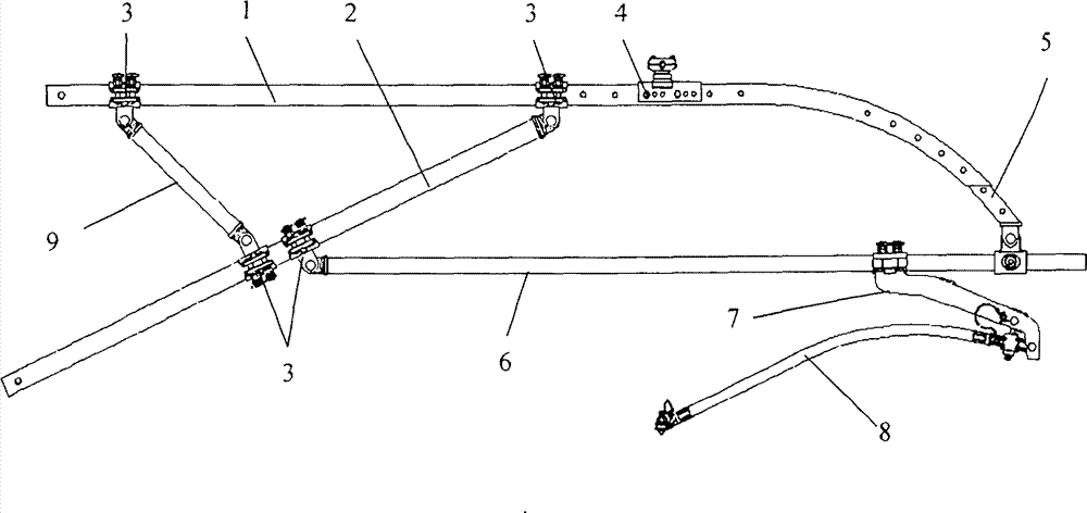
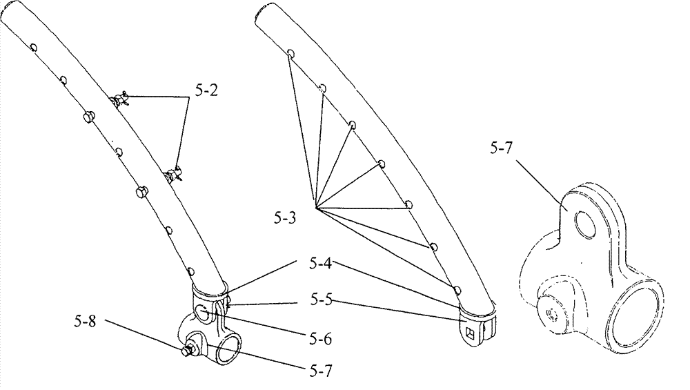
[0058] The structure of the anti-positioning adjustable wrist arm of the present invention, such as figure 1 shown. Including the horizontal arm 1, the structure of the horizontal arm 1 is as follows figure 2 , the right end of the horizontal wrist arm 1 is bent into an arc, and the radius of the arc in the center of the arc is 1000mm. At least five bolt holes B1-3 with a certain distance are processed side by side on the wall tube of the arc section, and at least two of them are A bolt hole B1-3 is fixedly connected with the adjusting device 5 arranged on the right end of the horizontal arm 1 through the bolt assembly A5-2, and the position of the adjusting device 5 can be adjusted up and down along the arc center of the arc section of the horizontal arm 1. The structure of adjusting device 5 is as image 3 As shown in a, b, and c, it inc...


PUM


Abstract

The invention relates to a push-off mode adjustable cantilever of overhead contact line equipment of an electrified railway, which comprises a horizontal cantilever, wherein six through holes are formed on the horizontal cantilever side by side; a catenary wire base is fixedly connected to the horizontal cantilever; the right end is bended into an arc shape; five through holes are formed on an arc section and are used for fixedly connecting an adjusting device; the horizontal cantilever is fixedly connected with two positioning rings, one of the positioning rings is connected with one end of an inclined cantilever, the inclined cantilever and the horizontal cantilever are arranged in the same direction to form an included angle, and the other positioning ring is connected with one end of a cantilever support; and the inclined cantilever is fixedly connected with two positioning rings, one of the positioning rings is connected with one end of a horizontal positioning pipe, the other end of the horizontal positioning pipe is connected with the adjusting device, the horizontal positioning pipe is fixedly connected with a positioner supporting base, the positioner supporting base is fixedly connected with one end of an elastic limiting positioner, and the other end of the elastic limiting positioner is fixedly connected with a positioning cable clamp. The push-off mode adjustable cantilever is used at a push-off mode position of the overhead contact line equipment of the electrified railway and is used for fixedly supporting a contact wire and a catenary wire, stabilizing the overhead contact line equipment, and preventing offline accidents.

Description

technical field [0001] The invention belongs to the technical field of electrified railway catenary, relates to a wrist arm positioning device, in particular to a reverse positioning adjustable wrist arm of electrified railway catenary. Background technique [0002] In the wrist-arm structure of the electrified railway catenary system, the contact wire and catenary wire sag under the action of its own weight, resulting in the unsteady contact of the pantograph and affecting the current flow. Therefore, the wrist-arm positioning device is used to support the contact wire and catenary cable Keep it in a horizontal state to ensure that the locomotive receives current. The wrist-arm positioning device is divided into positive positioning wrist-arm device and reverse positioning wrist-arm device, wherein the reverse positioning wrist-arm device is used to support contact suspensions such as catenary cables and contact lines at the reverse positioning, and to transfer loads. [0...

Claims


Application Information

Patent Timeline
Patent Type & Authority Patents(China)
IPC IPC(8): B60M1/20
Inventor 李霁开
Owner SHAANXI FLYWHEEL HIGH SPEED RAIL EQUIP CO LTD
Learn More