Alumina conveying system and method

A conveying system, alumina technology, applied in the direction of alumina/aluminum hydroxide, conveyor objects, transportation and packaging, etc., can solve the problem of fast wear of the conveying system, high energy consumption of the pneumatic lifting device, increase of intermediate links and energy consumption, etc. problems, to achieve the effect of reducing transmission links, reducing power consumption, and reducing wear and tear

Inactive Publication Date: 2010-04-28
HANGZHOU JINJIANG GROUP
View PDF0 Cites 9 Cited by
  • Summary
  • Abstract
  • Description
  • Claims
  • Application Information

AI Technical Summary

Problems solved by technology

[0006] 1. The use of belt conveyors increases intermediate links and energy consumption;
[0007] 2. The air lifting device consumes a lot of energy;
[0008] 3. The pneumatic lifting device conveys high hardness materials, and the conveying system wears quickly

Method used


Image

  • Alumina conveying system and method
  • Alumina conveying system and method
  • Alumina conveying system and method

Examples


Embodiment 1

[0022] Test run the method of the present invention in certain alumina factory.

[0023] Configure a B800×46450mm steel wire belt bucket elevator (N-TGD type, Hefei Cement Research and Design Institute), configure a motor Y280S-4 / 75kw, design a conveying capacity of 500t / h, and a lifting height of 45 meters, close to alumina The silo is set up and equipped with 2 pneumatic chutes. Constitutes the delivery system for alumina.

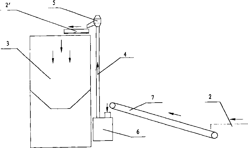
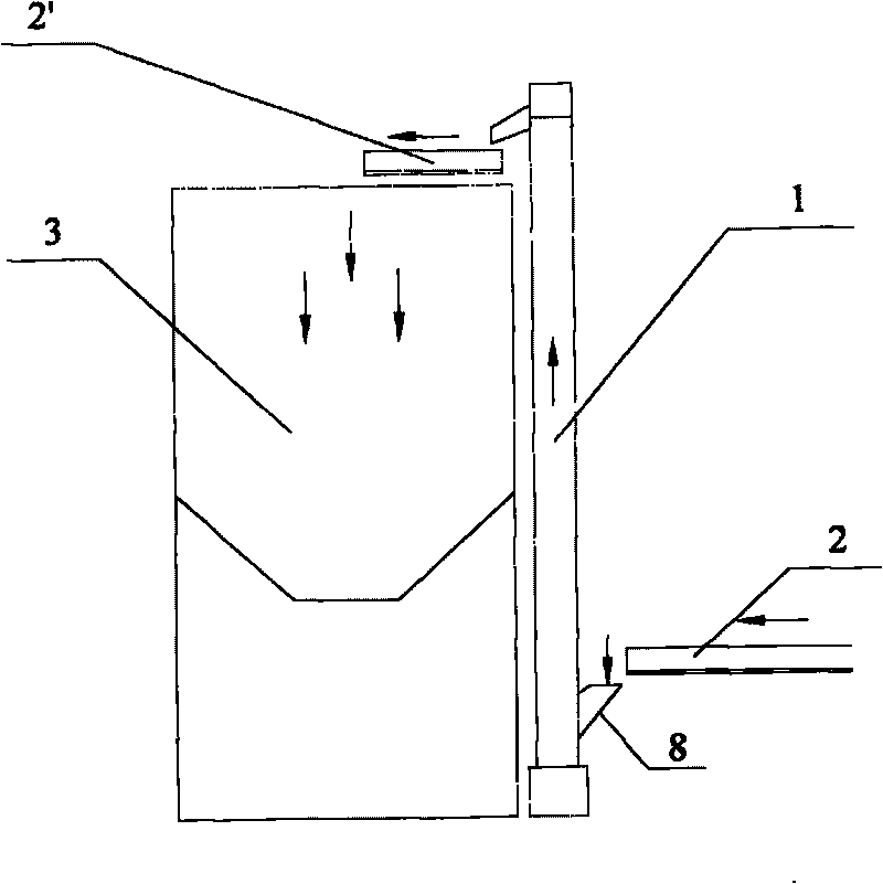
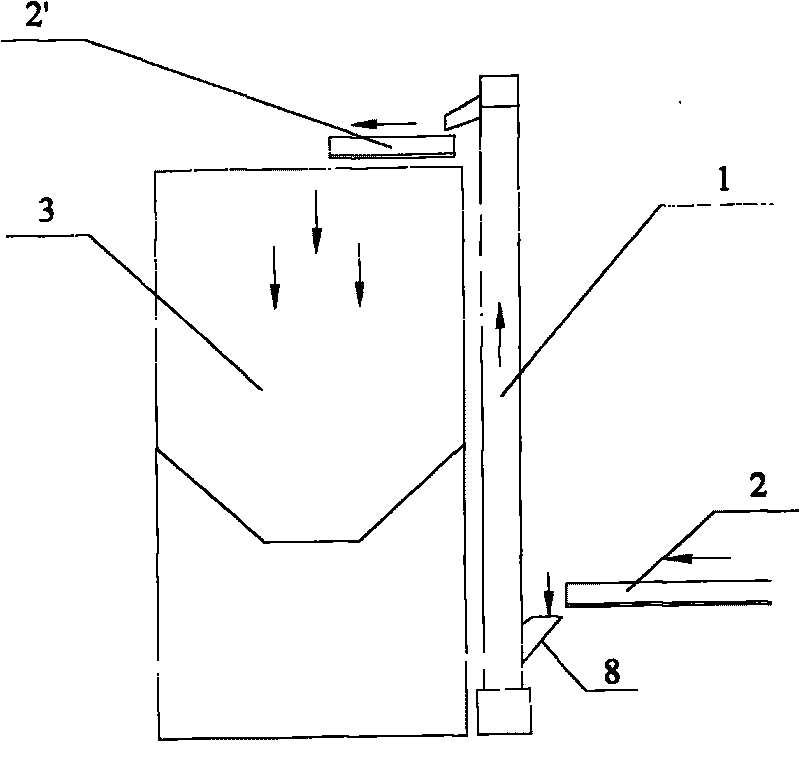
[0024] Such as figure 2 As shown, the alumina conveying system includes chute I 2, bucket elevator 1 and chute II 2', chute I 2 is used to convey alumina to the drop hopper 8 of bucket elevator 1, which is next to the alumina The silo 3 is set to lift the alumina to the top of the alumina silo 3; the chute II 2' is set on the top of the alumina silo 3, and is used to send the alumina lifted to the top of the alumina silo 3 Alumina silo 3.

[0025] The finished alumina product is directly transported to the hopper 8 of the steel belt type bucket elev...


PUM


Abstract

The invention relates to an alumina conveying system and method, including directly conveying alumina to the hopper of a bucket type hoister from chute and hoisting the alumina to top of alumina bin by the bucket type hoister. The invention conveys alumina by utilizing a bucket type hoister instead of a pneumatic hoisting device initially in alumina production, thus greatly reducing power consumption of hoisting alumina vertically; besides a travelling apron is spared, conveying link is reduced, and horizontal conveying power consumption is reduced; and dynamic conveying is changed into static conveying, thus greatly reducing abrasion in conveying process. Practice shows that power is reduced to 75kW from original 185kWx2 under the conditions that conveying capacity is 300t / h and material is hoisted to the top of alumina bin by utilizing a steel wire adhesive tape bucket type hoister instead of a pneumatic hoisting device.

Description

technical field [0001] The invention relates to an alumina production process, in particular to a system and method for conveying alumina. Background technique [0002] In alumina production, alumina products are generally transported to the belt conveyor by means of a pneumatic chute, and then transported to the pneumatic lifting device by the belt conveyor, and then vertically transported to the alumina warehouse by using the pneumatic vertical conveying device. [0003] The existing technology uses a pneumatic lifting device to transport alumina products, which is a great improvement compared to the traditional method of transporting the belt conveyor, reducing investment and increasing production capacity, and because gas is used as the medium for transporting products, it will not cause pollution with products, and has the advantages of Its outstanding advantages. [0004] The core device of the pneumatic lifting vertical conveying device is the pneumatic lifting pump....

Claims


Application Information

Patent Timeline
Patent Type & Authority Applications(China)
IPC IPC(8): C01F7/02B65G65/32B65G47/16B65G47/34
Inventor 钭正刚陈晓帆
Owner HANGZHOU JINJIANG GROUP
Why Eureka
Try Eureka