
Coupler

A coupling and half-coupling technology, applied in the direction of couplings, rigid shaft couplings, mechanical equipment, etc. Due to the problems of compactness and low coupling strength, it achieves the effect of high manufacturing precision, simple structure and compact combination.

Inactive Publication Date: 2010-04-28
SHENNAN CIRCUITS
View PDF0 Cites 12 Cited by
  • Summary
  • Abstract
  • Description
  • Claims
  • Application Information

AI Technical Summary

Problems solved by technology

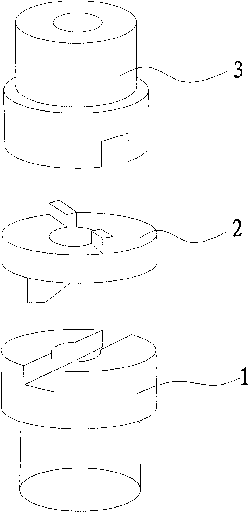
[0003] However, the manufacturing precision of the first half-coupling 1 and the second half-coupling 3 of the coupling is high, and the two half-couplings need to be connected through the connector 2, the strength of the coupling is not large, and The coupling formed by the first half-coupling 1 and the second half-coupling 3 connected by the connecting head 2 is not compact in axial length, and is suitable for special (acid, alkaline) application environments in the PCB industry. In the middle, it is inconvenient to disassemble, and it is easy to cause the two halves of the coupling to be disconnected from the connector 2, and the connection is not smooth

Method used


Image

  • Coupler
  • Coupler
  • Coupler

Examples


Embodiment Construction

[0021] In order to describe the technical content, structural features, achieved objects and effects of the present invention in detail, the following detailed description is given in conjunction with the embodiments and the accompanying drawings.

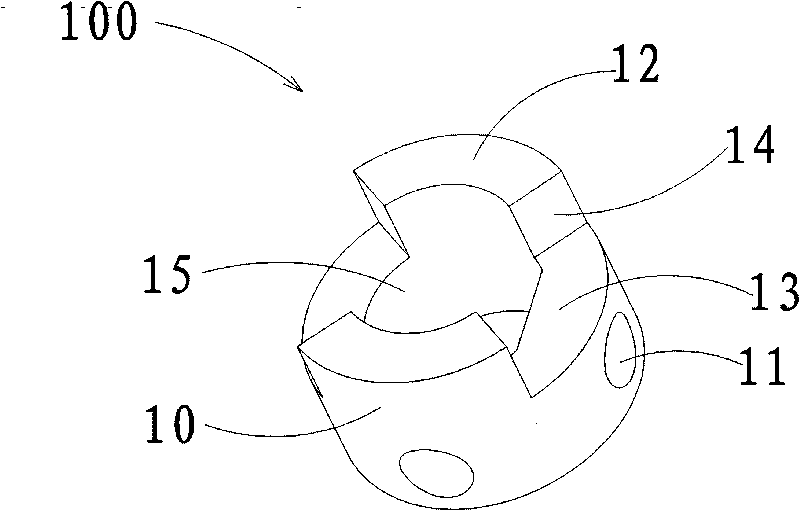
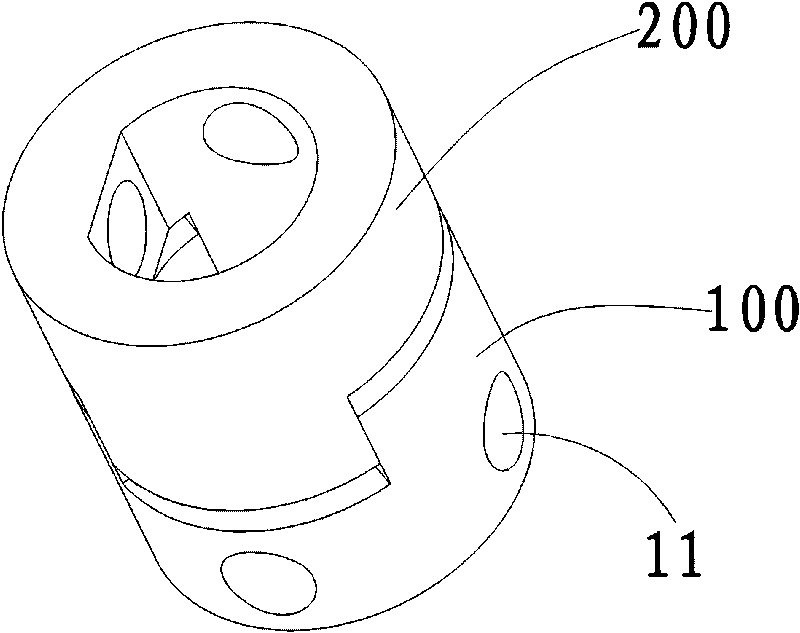
[0022] see figure 2 and image 3 , which is an embodiment of the coupling of the present invention, including a first half coupling 100 and a second half coupling 200, the first half coupling 100 and the second half coupling 200 have complete the same structure. The first half coupling 100 has a cylindrical coupling body 10, the coupling body 10 has a positioning hole 15 penetrating the upper and lower end surfaces of the coupling body 10, the positioning hole 15 is formed by A closed figure formed by a chord and a straight line or a closed figure formed by arcs with different radii. In this embodiment, the positioning hole 15 is in the shape of a moon or a polygon. The side edge of the coupling body 10 is provided with a slot ...


PUM


Abstract

The invention discloses a coupler which comprises a first half coupler and a second half coupler which are provided with coupling bodies; the coupling bodies are respectively provided with a locating hole passing through the upper and the lower end surfaces of the coupling bodies; at least two convex blocks extends at one end of the coupling bodies in a convex way, and an inserting hole is formed between the two adjacent convex blocks; and the convex block and the inserting hole of the first half coupler can be blocked and jointed with the inserting hole and the convex block of the second half coupler. As the convex block of the first half coupler and the convex block of the second half coupler are blocked and jointed with each other in a crossing way, the coupler has simple structure, easy fabrication, convenient assembly and compact combination. Furthermore, as the coupling bodies of the first half coupler and the second half coupler are provided with the locating holes which are matched with shaft ends of connected shaft bodies, the combination is firm, and the coupling bodies and the connected shaft bodies can be prevented from sliding.

Description

technical field [0001] The present invention relates to a shaft coupling, in particular to a shaft coupling arranged coaxially for transmitting torque of two shafts. Background technique [0002] Couplings are mechanical parts used to connect two shafts in different mechanisms to rotate together to transmit torque. see figure 1 , which is an existing coupling, including a first half coupling 1 , a second half coupling 3 , and a connecting head 2 connecting the first half coupling 1 and the second half coupling 3 . The central position of the upper end face and the central position of the lower end face of the connecting head 2 are respectively provided with convex heads, and the upper end face of the first half coupling 1 and the lower end face of the second half coupling 3 are respectively provided. There is an insert groove matching the convex head, and the convex head is embedded in the insert groove, so as to connect the first half-coupling 1 and the second half-coupli...

Claims


Application Information

Patent Timeline
Patent Type & Authority Applications(China)
IPC IPC(8): F16D1/112
Inventor 栾红军
Owner SHENNAN CIRCUITS
Learn More