MEMS micropump-based solid-liquid composite lubricated shafting for flywheel

A technology of solid-liquid compounding and lubricating shafts, which is applied in the direction of engine lubrication, bearing components, shafts and bearings, etc., can solve the problems of large friction torque and low control precision, improve the initial running-in, improve control precision, and improve the prevention of starting bite effect

Inactive Publication Date: 2010-04-28
CHANGCHUN INST OF OPTICS FINE MECHANICS & PHYSICS CHINESE ACAD OF SCI
View PDF0 Cites 8 Cited by
  • Summary
  • Abstract
  • Description
  • Claims
  • Application Information

AI Technical Summary

Problems solved by technology

[0006] Aiming at the problems of large friction torque near zero speed, severe wear, and low control precision in current flywheels, the present invention provides a solid-liquid composite lubrication shaft system for space flywheels based on MEMS micropumps, which can be used for inner rotor flywheel motors and The outer rotor flywheel motor provides effective support, through the use of MEMS micropore-enhanced solid film lubricated ceramic bearings + MEMS micro-pump liquid compound lubrication method for precise oil supply, the shaft lubrication system adopts a cavity oil reservoir-MEMS micro-pump-labyrinth The oil storage, oil supply and holding device composed of seals make the shafting have good lubricating and frictional characteristics in a wide speed range from static start to high-speed operation, effectively improve the initial run-in and prevent start-up seizure, and at the same time improve the shafting performance. Control accuracy, service life and reliability near zero speed

Method used


Image

  • MEMS micropump-based solid-liquid composite lubricated shafting for flywheel
  • MEMS micropump-based solid-liquid composite lubricated shafting for flywheel
  • MEMS micropump-based solid-liquid composite lubricated shafting for flywheel

Examples


Embodiment Construction

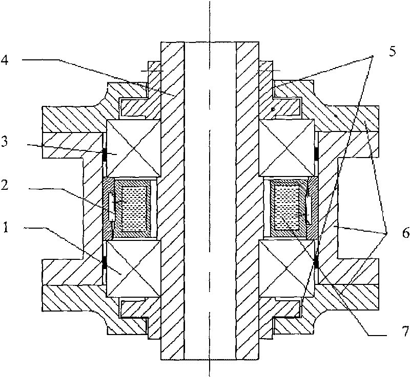
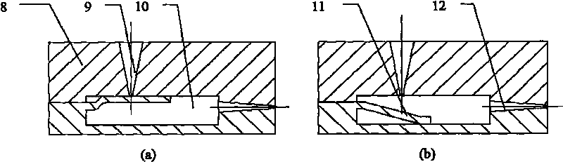
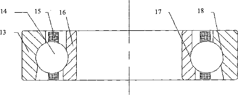
[0013] Such as figure 1 As shown, the inner rings of the first MEMS micropore-reinforced solid film lubricated ceramic bearing 1 and the second MEMS micropore-reinforced solid film lubricated ceramic bearing 3 of the key supporting parts of the shaft system are respectively tightly mounted on the shaft shoulders, and both ends are supported by inner rings. The support sleeve 5 is fixed, and the outer support sleeve 6 preloads the bearing; it is applied to the inner rotor flywheel motor, and the motor rotor is connected to the inner support sleeve 5; it is applied to the outer rotor flywheel motor, and the motor rotor is connected to the outer support sleeve 6. MEMS micro-pump oil storage-oil supply system 2 can accurately control the oil supply volume and oil supply speed through the wedge-shaped micro-oil inlet 9 and micro-valve 11 made by MEMS technology by virtue of the centrifugal force during work. Improve the utilization rate of lubricating oil and increase the lubricati...


PUM


Abstract

The invention belongs to the technical field of space tribology, and relates to an MEMS micropump-based solid-liquid composite lubricated shafting for a flywheel. The shafting comprises a first MEMS micropore reinforced solid film lubricated ceramic bearing, an MEMS micropump oil storage-oil supply system, a second micropore reinforced solid film lubricated ceramic bearing, a main shaft, an internal support sleeve, an external support sleeve and an oil reservoir. The shafting can provide effective support and lubrication for an internal rotor motor and an outer rotor motor, and utilizes a liquid composite lubrication mode that the MEMS micropore reinforced solid film lubricated ceramic bearings and an MEMS micropump supply oil accurately. A shafting lubricating system adopts an oil storage device, an oil supply device and a maintaining device which consist of a cavity oil reservoir, the MEMS micropump and a labyrinth seal to make the shafting have excellent lubrication properties and friction properties within the wide rotating speed range from static starting to high-speed operation, so that the initial running is improved effectively, the starting occlusion is prevented, and simultaneously, the control accuracy, service life and reliability of the shafting are improved at low speed.

Description

technical field [0001] The invention belongs to the technical field of space tribology, and relates to a solid-liquid composite lubricating shaft system for a flywheel based on a MEMS micropump. Background technique [0002] The development of satellites requires that the attitude control system has high precision and long life and can provide precise control torque, so more and more flywheel three-axis attitude stabilization systems are used. The space attitude control flywheel is generally composed of a rotor, a shaft system, a brushless DC motor and a sealed casing. Shafting is a key component in the flywheel, and its design directly determines the control accuracy, reliability and life of the flywheel. [0003] Flywheels for attitude control are divided into two types: offset momentum wheels and reaction flywheels. The average speed of the offset momentum wheels is generally 2000-3000 rpm, and the flywheel rotates in one direction; rotate in one direction. Compared wi...

Claims


Application Information

Patent Timeline
Patent Type & Authority Applications(China)
IPC IPC(8): F16N7/40F16C35/12F16C33/58B64G1/24
Inventor 白越吴一辉黄敦新
Owner CHANGCHUN INST OF OPTICS FINE MECHANICS & PHYSICS CHINESE ACAD OF SCI
Why Eureka
Try Eureka