Quenching machine

A quenching machine and frame technology, applied in the field of quenching machines, can solve the problems of time-consuming and laborious, difficult correction of workpiece deformation errors, pollution, etc.

Inactive Publication Date: 2010-05-05
HUAPENG GRP
View PDF4 Cites 6 Cited by
  • Summary
  • Abstract
  • Description
  • Claims
  • Application Information

AI Technical Summary

Problems solved by technology

This method is easy to cause bending and deformation of the workpiece, which affects the machining accuracy of the workpiece. It is difficult to correct the deformation error of the workpiece after quenching. It can only be leveled by manual beating. However, manual beating is t

Method used


Image

  • Quenching machine
  • Quenching machine

Examples


Embodiment Construction

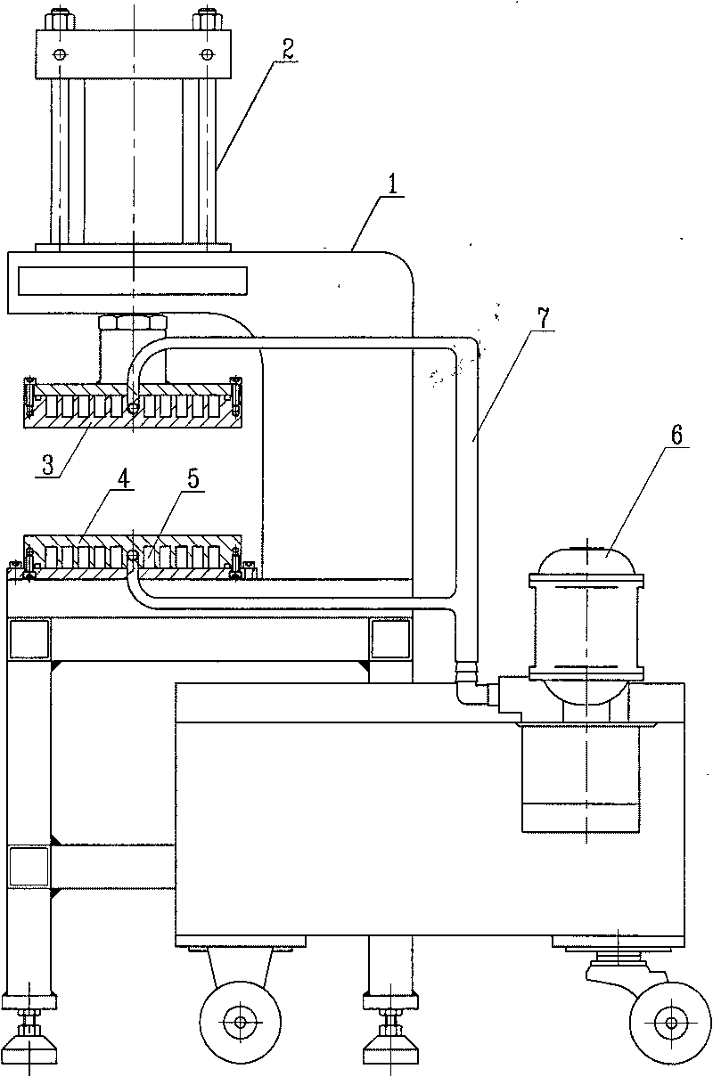
[0009] As shown in the figure, the quenching machine of the present invention includes a frame 1, a cylinder 2, an upper platen 3, a lower platen 4, a water tank 5, a water pump 6 and a water circulation system 7, and the cylinder 2 is vertically fixed on the top of the frame 1, and the cylinder 2 The piston rod passes through the upper arm of the frame 1, and is fixedly connected to the upper platen 3 at the end, and the lower platen 4 is fixed on the workbench of the frame 1, and coincides with the upper platen 3 in the vertical direction, and the work of the upper platen 3 The surface is opposite to the working surface of the lower platen 4, and the back of the upper platen 3 and the lower platen 4 are provided with a water tank 5, which is connected with the water circulation system 7, and a water pump 6 is arranged in the water circulation system 7 to ensure cooling in the water circulation system 7. liquid circulation.

[0010] When the present invention works, the workp...


PUM


Abstract

The invention relates to a quenching machine comprising a stand, a cylinder, an upper pressure plate, a lower pressure plate, sinks, a water pump and a water circulation system. The cylinder is vertically fixed at the top of the stand; a cylinder piston rod penetrates through an upper arm of the stand and is fixedly connected with the upper pressure plate at one end part; the lower pressure plate is fixed on a stand worktable and superimposed on the upper pressure plate in a vertical direction; the working surfaces of the upper pressure plate and the lower pressure plate are opposite; and the sinks are arranged at the backs of the upper pressure plate and the lower pressure plate and connected with the water circulation system which is provided with the water pump to ensure the circulating flow of cooling liquid in the water circulation system.

Description

technical field [0001] The invention relates to a quenching machine among equipment in the machinery manufacturing industry, which is applied to the quenching process in the processing of various precision metal parts. Background technique [0002] The existing quenching method for metal parts is: heating the workpiece to a specified temperature, and directly cooling it in water or oil. This method is easy to cause bending and deformation of the workpiece, which affects the machining accuracy of the workpiece. It is difficult to correct the deformation error of the workpiece after quenching. It can only be leveled by manual beating. However, manual beating is time-consuming and laborious, and the beating process also produces large noise pollution. The beating method also directly affects the appearance quality of the product, and even produces internal stress, which is prone to breakage during assembly, making the workpiece unusable. Contents of the invention [0003] Th...

Claims


Application Information

Patent Timeline
IPC IPC(8): C21D9/00
Inventor 金正风陈云华
Owner HUAPENG GRP
Why Eureka
Try Eureka