

High-speed electric main shaft dynamic rigidity test device
A high-speed motorized spindle and dynamic stiffness technology, applied in the direction of machine gear/transmission mechanism testing, etc., can solve the problems of inability to meet the performance testing requirements of high-speed motorized spindle, inability to achieve non-destructive loading, difficult control and testing, etc., and achieve real-time measurement. , stable dynamic loading, low difficulty effect
- Summary
- Abstract
- Description
- Claims
- Application Information
AI Technical Summary
Problems solved by technology
Method used
Image

Examples
Embodiment Construction
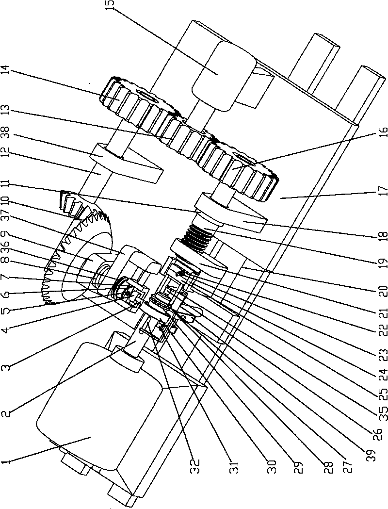
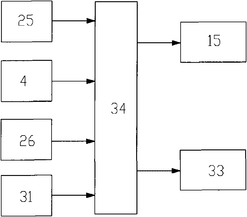
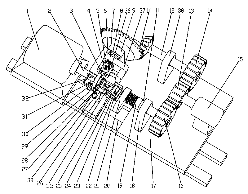
[0023] figure 1 It is a schematic diagram of the structure of the present invention, figure 2 It is the control schematic diagram of the present invention, as shown in the figure: the high-speed electric spindle dynamic stiffness testing device of this embodiment includes a base 17, a loading system and an automatic control unit 34;
[0024] The loading system includes an axial loading system, a radial loading system and a test rod 2 fixedly arranged on the high-speed electric spindle 1;
[0025] The outer circle of the test rod 2 is provided with a radial rolling bearing 30, and the loading end of the test rod 2 is provided with a plane rolling bearing 27;
[0026] Described axial loading system comprises axial loading rod 35 and axial loading driving system, and axial loading driving system comprises axial loading servo motor, axial loading driving screw rod 19 and axial loading driving nut 21, and described axial loading The drive screw 19 is in transmission cooperation ...
PUM
 Abstract
Description
Claims
Application Information