
Calibrating method for big modulation bandwidth linear FM signal frequency response

A technology of linear frequency modulation signal and frequency modulation signal, which is applied in the field of testing, can solve problems such as the influence of accuracy calibration effect, complex calibration process, and inability to implement real-time calibration, and achieve the effect of full-channel calibration and real-time calibration

Active Publication Date: 2010-05-05
CHINA ELECTRONIS TECH INSTR CO LTD
View PDF0 Cites 26 Cited by
  • Summary
  • Abstract
  • Description
  • Claims
  • Application Information

AI Technical Summary

Problems solved by technology

It can be seen that the accuracy of external measuring instruments and standard comparison parts, and the error of the algorithm will have a great impact on the calibration effect. At the same time, the complicated calibration process is not conducive to the efficient production of chirp modules.
In addition, due to the need for measuring instruments and standard comparison parts, this method cannot implement real-time calibration at the user's site

Method used


Image

  • Calibrating method for big modulation bandwidth linear FM signal frequency response
  • Calibrating method for big modulation bandwidth linear FM signal frequency response
  • Calibrating method for big modulation bandwidth linear FM signal frequency response

Examples


Embodiment Construction

[0051] The present invention will be described in further detail below in conjunction with the accompanying drawings.

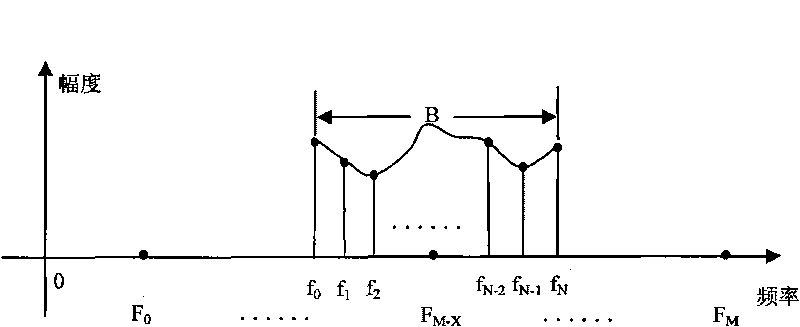
[0052] In a narrow sense, radio frequency signals are figure 1 The signal generated by the "radio frequency signal" module shown, in a broad sense, the above signal will be used as the final output signal of the device after a series of conditioning, and the output signal can also be called a radio frequency signal; a large modulation bandwidth chirp signal refers to figure 1 The signal generated by the linear frequency modulation signal generation module. The "Large Modulation Bandwidth Chirp Signal Frequency Response Calibration Method" proposed by the present invention is a method of adding a chirp signal to a system using a chirp signal, and calibrating the frequency response of the entire channel, leaving the equipment to be calibrated and The radio frequency signal generated by it cannot be discussed in this calibration method.

[0053] For example, a...


PUM


Abstract

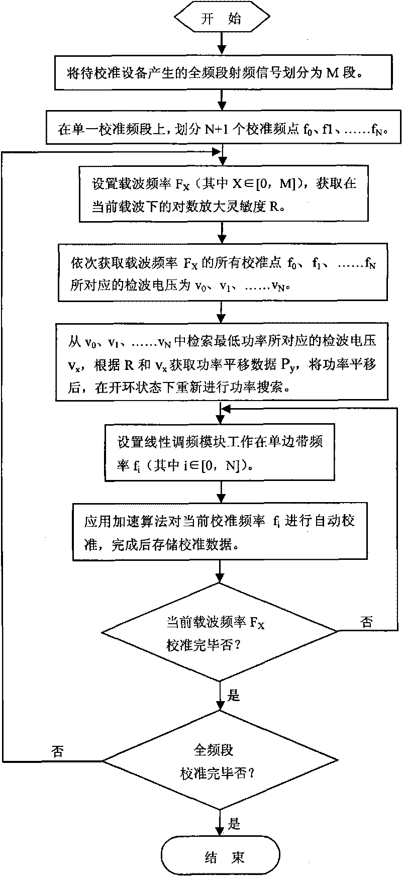
A calibrating method for big modulation bandwidth linear FM signal frequency response relates to the technical field of testing, comprising the steps of: 1) dividing a radio frequency signal in a complete frequency range generated by a calibrating device into a plurality of frequency sections F0 to F1, F1 to F2,..., FM-2 to FM-1 and FM-1 to FM, for calibrating section by section, 2) confirming N+1 calibrating points on a single calibrating frequency section, 3) dynamically acquiring a log amplifying sensitivity R, 4) translating and searching the smallest carrier power, and 5) automatically calibrating frequency points FM one by one. The method of the invention automatically calibrates and compensates basing on the linear FM signal frequency response of an interior detection circuit and an agility damping circuit in the calibrating device and the frequency response calibration can be automatically performed without an additional testing and calibrating device for user to perform real time calibration on site. The detection circuit and the agility damping circuit are both located in a modulating channel, so not only the frequency response of linear FM signal generating module is calibrated but also the whole passage is calibrated.

Description

technical field [0001] The invention relates to the technical field of testing, in particular to a method for calibrating the frequency response of a linear frequency modulation signal with a large modulation bandwidth. Background technique [0002] Linear frequency modulation (LFM or Chirp) is the earliest and most mature pulse compression technology, which was proposed as early as the late 1940s. One of the outstanding advantages of this signal is that it can match The filter is not sensitive to the Doppler frequency shift of the echo signal, which greatly simplifies the requirements for the subsequent signal processing system, so it is widely used in the fields of radar, signal simulation and test instruments. [0003] Chirp signals are widely used in the field of radar and testing technology. FM frequency response is an important indicator of the amplitude-frequency characteristics of chirp signals, which describes the amplitude fluctuations in the effective frequency ba...

Claims


Application Information

Patent Timeline
Patent Type & Authority Applications(China)
IPC IPC(8): G01S7/40
Inventor 樊晓腾左永锋何攀峰刘盛时慧
Owner CHINA ELECTRONIS TECH INSTR CO LTD
Learn More