
Optical track capturing input device

An input device and optical technology, applied in the input/output process of data processing, instruments, electrical digital data processing, etc., can solve the problems of high production cost, difficulty in universal acceptance, and damage to the operator's eyesight, and achieve power consumption Small, easy to master, simple and easy to input

Inactive Publication Date: 2010-05-05
上海思佗科自动化科技有限公司
View PDF0 Cites 13 Cited by
  • Summary
  • Abstract
  • Description
  • Claims
  • Application Information

AI Technical Summary

Problems solved by technology

However, these inventions require complex neural network algorithms, etc., and consume huge computing resources. Their production costs are extremely high, and it is difficult to obtain general acceptance in the market.
[0004] As for the virtual keyboard, it is a broken input process of input, error correction, and confirmation input. From the perspective of user experience, its input efficiency is relatively low; at the same time, the virtual keyboard uses a visible laser light to indicate the input content, which will affect the operator's vision. cause some damages

Method used


Image

  • Optical track capturing input device
  • Optical track capturing input device
  • Optical track capturing input device

Examples


Embodiment Construction

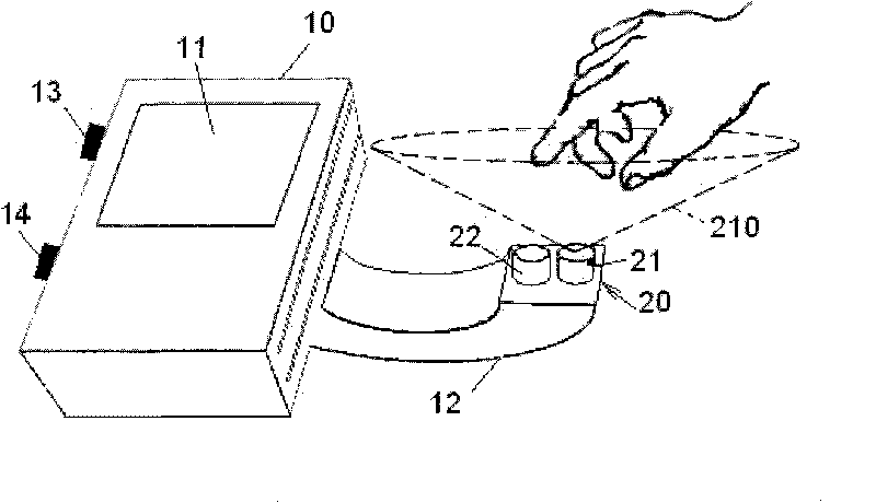
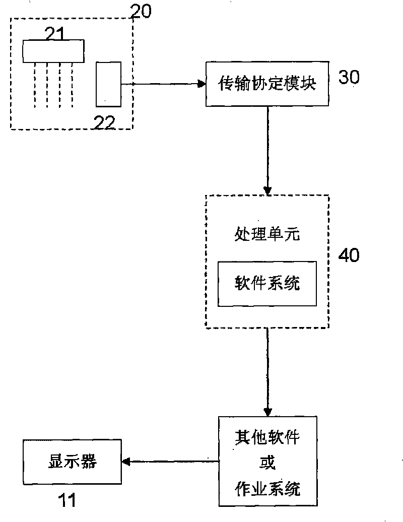
[0020] For the first preferred embodiment of the present invention, please refer to figure 1 As shown, it includes a carrier 10, which can be the casing of the input device or the shell of a generalized computer device, and the carrier 10 is provided with a display 11, which may be the display of the generalized computer device itself, Furthermore, a support arm 12 extends from the carrier 10 on one side, and an optical sensing module 20 is provided on the end of the support arm 12. In this embodiment, the optical sensing module 20 includes:

[0021] More than one scattered light source 21 is used to scatter and emit a weak visible light that can be directly seen or an infrared light source that is invisible and non-destructive to eyesight. When multiple light sources are used, each light source is emitted at the wrong time and has a certain code to Avoid mutual interference; in the embodiment, a scattering light source is used, and the scattering light source is projected upward ...


PUM


Abstract

The invention relates to an optical track capturing input device which mainly uses optical sensing equipment and software operation technology to judge the actions of mouse moving, typing, click, double click, hand writing and the like of users by capturing the data such as distance, depth and the like of simple actions of moving, touching and the like generated by fingers or other objects, thereby achieving the purpose that users can carry out various kinds of input operations on electronic equipment, such as mobile phones, various micro hand-held computers, personal computers, graphic workstations, televisions and the like.

Description

Technical field [0001] The invention relates to an optical track capture input device, in particular to a method of optical and image processing technology to simulate the input actions of an operator to a generalized computer equipment. Background technique [0002] The existing optical mouse on the market was invented in 1981 and applied for a patent. The optical mouse has been widely used in narrowly defined computer devices (such as personal computers) that do not need to move and have an operating plane, and has created hundreds of millions of sales. However, the optical mouse still needs a fixed operating plane in use, but for generalized computer equipment or home appliances with computers, it may have to have the characteristics of being movable and no operating plane is available, so it must be An optical mouse used on an operating plane cannot meet the requirements of generalized computer equipment to perform input actions. It cannot be applied to the more and more wi...

Claims


Application Information

Patent Timeline
IPC IPC(8): G06F3/033
Inventor 文华
Owner 上海思佗科自动化科技有限公司
Learn More