Circular polarization waveguide standing-wave antenna

A circularly polarized wave and standing wave technology, applied in slot antennas, circuits, etc., can solve problems such as low efficiency and beam pointing changes with frequency, and achieve the effect of easy tracking and easy control

Active Publication Date: 2010-05-05
CHINA ELECTRONIC TECH GRP CORP NO 38 RES INST
View PDF2 Cites 27 Cited by
  • Summary
  • Abstract
  • Description
  • Claims
  • Application Information

AI Technical Summary

Problems solved by technology

[0007] In order to solve the problems of the low efficiency of the existing circularly polarized waveguide slot traveling wave antenna, the beam pointing varies with frequency, etc., the present invention provides a circularly polarized waveguide standing wave antenna

Method used


Image

  • Circular polarization waveguide standing-wave antenna
  • Circular polarization waveguide standing-wave antenna
  • Circular polarization waveguide standing-wave antenna

Examples


Embodiment 1

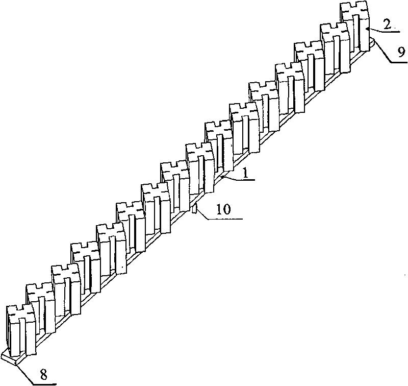
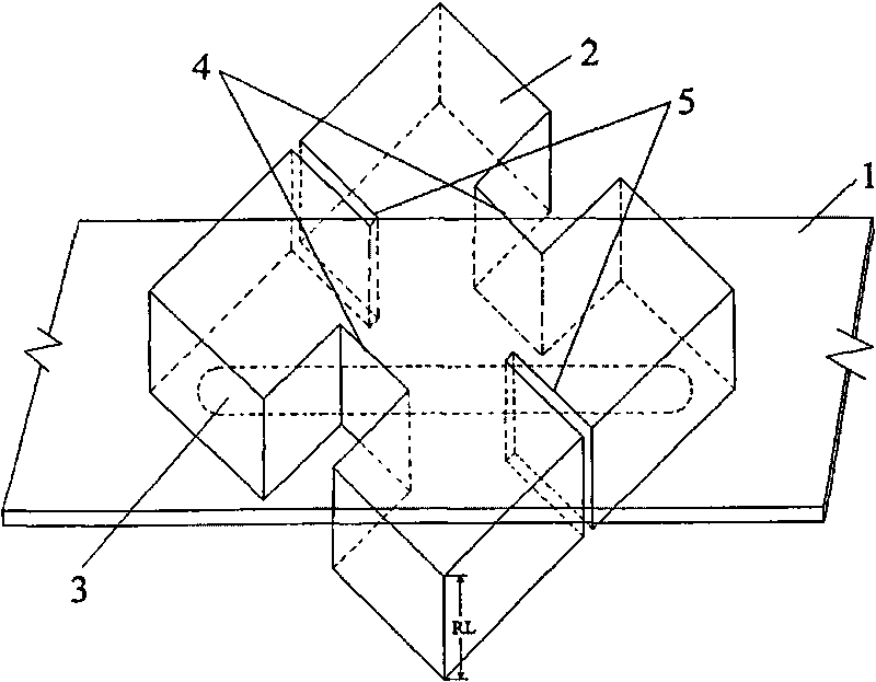
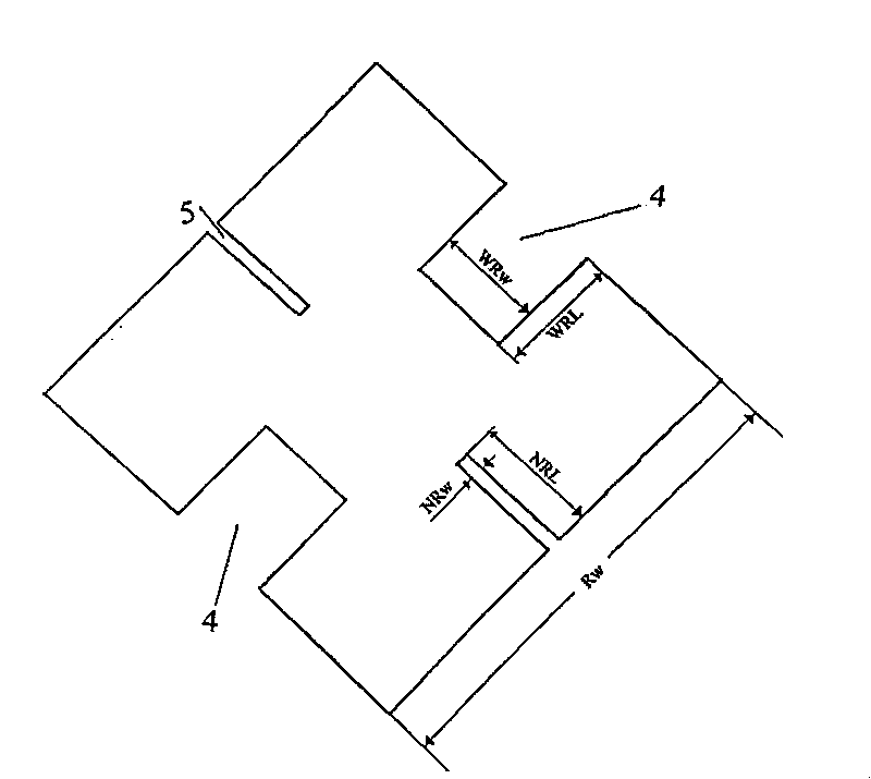
[0029] A preferred embodiment of the present invention is a 16-element circularly polarized waveguide standing wave antenna array according to the evenly distributed Ka band, and the central operating frequency is f 0 =24.5GHz, see Figure 1-Figure 5 , the circularly polarized waveguide standing wave antenna includes a feeding waveguide 1, the cross-section of the feeding waveguide 1 is rectangular, and 16 coupling slots 3 are evenly arranged on both sides of the longitudinal broadside center line of the feeding waveguide 1. A coaxial connector 10 (SMA) is provided in the middle of one side of the feed waveguide 1; 16 four-ridge metal ridge radiation waveguides 2 are provided at the coupling slot 3 on the broad side of the feed waveguide 1; the four-ridge metal The ridge radiation waveguide 2 and the feeding waveguide 1 form a "T"-shaped structure, and the diagonals of the four-ridge metal ridge radiation waveguide mouth face and the coupling slot 3 are on a straight line.

...

Embodiment 2

[0039] Another preferred embodiment of the present invention is Image 6 As shown, the 24×16 waveguide antenna subarray consists of figure 1 The 16-element linear array shown is formed by translation along the same direction. This sub-array is connected with T / R components, supplemented by power supply, wave control and installation structural parts, etc., which can be expanded into a large-scale sub-array-level active phased array antenna.

Embodiment 3

[0041] Another preferred embodiment of the present invention is a 16-unit waveguide standing wave circularly polarized antenna array distributed by Taylor, and its structural shape is the same as that of Embodiment 1, and the main differences are as follows:

[0042] The length SL of each coupling slot 3 is different from the distance Sp from the broadside centerline of the feeding waveguide 1, that is, the distances of the four-ridge metal ridge radiation waveguide 2 from the broadside centerline of the feeding waveguide 1 are different, and the selection method of the value is as follows Known by professionals in the industry.


PUM


Abstract

The invention relates to a circular polarization waveguide standing-wave antenna which solves the problems of low efficiency, wave beam orientation changed along with the frequency and the like of the prior circular polarization waveguide gap traveling-wave antenna. Both sides of the center line of the longitudinal wide edge of a feed waveguide tube with a rectangular cross section are evenly distributed and provided with more than two coupling gaps in a staggered way, and the middle part of the wide edge at one side of the feed waveguide tube is provided with a coaxial connector; both ends of the feed waveguide tube are sealed, a four-ridge metal ridge radiation waveguide is arranged at the coupling gaps at the wide edge of the feed waveguide tube, and the diagonal line of the opening face of the four-ridge metal ridge radiation waveguide and the coupling gaps are on the same straight line. The invention can realize that energy enters a waveguide cavity and is completely radiated out, and the radiation efficiency of the antenna is greatly enhanced; the problem of inconsistent orientation of wave beams with different working frequencies of the waveguide traveling-wave antenna is solved, and the tracking of the antenna to a satellite is easy.

Description

technical field [0001] The invention relates to an improved structure of a circularly polarized waveguide antenna, in particular to a circularly polarized waveguide standing wave antenna. The invention can be used both for receiving and for transmitting circularly polarized radio waves. It can be used as a mobile terminal antenna in the field of satellite communication. Background technique [0002] In recent years, with the vigorous development of satellite communications, antennas used in satellite broadcasting, television, communication and data transmission systems have developed rapidly, and the demand for various antennas has also increased rapidly, which has promoted its development. [0003] For the antenna system of mobile satellite live broadcast communication, it is usually installed on the top of the plane, car or train. Based on the high maneuverability of the platform, the requirements for the antenna are also very high, such as: miniaturization, low profile, ...

Claims


Application Information

Patent Timeline
Patent Type & Authority Applications(China)
IPC IPC(8): H01Q13/10
Inventor 张洪涛汪伟
Owner CHINA ELECTRONIC TECH GRP CORP NO 38 RES INST
Why Eureka
Try Eureka