
Intelligent illumination control system and method

A technology of intelligent lighting control and control method, which is applied in energy-saving control technology, lighting devices, signal transmission systems, etc., and can solve problems such as voltage instability, low power saving rate, and small system control capacity

Inactive Publication Date: 2010-05-05
宁波知睿节能技术有限公司
View PDF5 Cites 45 Cited by
  • Summary
  • Abstract
  • Description
  • Claims
  • Application Information

AI Technical Summary

Problems solved by technology

[0009] 2. Multiple switchgears are used to turn on, turn off, and reduce power of a single lamp in time-sharing, and the electromagnetic mode is used for step-down voltage reduction. Although a certain power-saving effect has been achieved, there are still energy and environmental problems due to the large consumption of materials. question
[0010] 3. The method of using the DALI standard protocol to realize the master-slave remote control has the disadvantages of short working distance and few slave nodes, resulting in a small system control capacity.
[0011] 4. The power-saving rate of the fixed step-down method is low, and it is easy to cause voltage instability, which seriously affects the service life of street lamps
[0012] 5. Most of the systems or equipment lack self-protection functions, or the protection functions are incomplete
[0013] 6. Lack of meteorological linkage, cable anti-theft alarm, dynamic electronic map display and other functions, the control function is single, it is difficult to meet the needs of modern urban street lamp construction

Method used


Image

  • Intelligent illumination control system and method
  • Intelligent illumination control system and method
  • Intelligent illumination control system and method

Examples


Embodiment 1

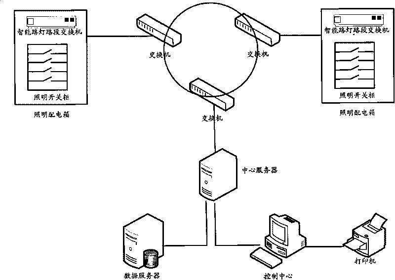
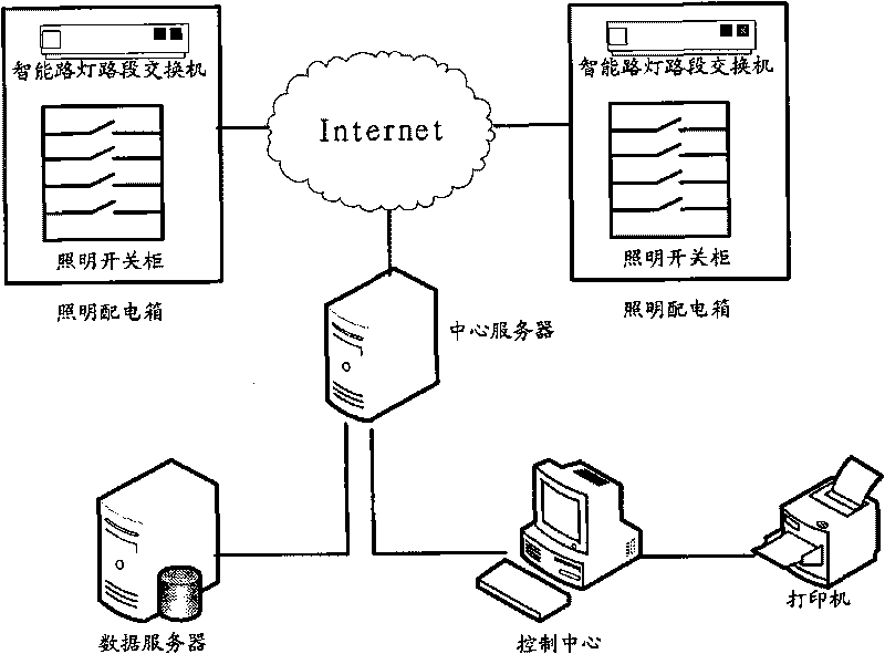
[0059] The invention discloses an intelligent lighting single-lamp single-point multi-control system, which can realize single-lamp multi-control, single or all control of multiple light sources with different functions on a lamp post; realize single-lamp power conversion, without changing existing products Change the existing power under the circumstances; realize single lamp control, control and power conversion when the user has the power conversion function; realize the independent operation of the remote control terminal; realize the remote geographical location display; realize the frequency conversion start / automatic voltage stabilization function ; Realize automatic / manual dimming; Realize scheme preset, real-time control, power monitoring, system failure alarm, statistical analysis and query, system maintenance and management.

[0060] see figure 1 , figure 2 , image 3 , Figure 4 and Figure 6 , the present invention discloses an intelligent lighting control sy...


PUM


Abstract

The invention discloses an intelligent illumination control system and a method. The system comprises a control center, at least one intelligent road-lamp road-section controller, at least one intelligent road-lamp terminal controller and a plurality of controlled objects; wherein the control center transmits control signals to the intelligent road-lamp road-section controllers and returns operating status parameters of all controlled devices including the controlled objects, the intelligent road-lamp terminal controllers and the intelligent road-lamp road-section controllers, and controls road lamps in all road sections, or road lamps in one road section / a plurality of road sections, or the controlled objects on one lamp post / a plurality of lamp posts; and each intelligent road-lamp road-section controller receives the control signal of the control center and status signals of the intelligent road-lamp terminal controller (to which the intelligent road-lamp road-section controller belongs) and the controlled objects, and controls the intelligent road-lamp terminal controller (to which the intelligent road-lamp road-section controller belongs) according to the control signal. The invention can realize controlling one point by multiple points: multiple light sources with different functions on the same lamp post can be controlled independently or entirely; and a single light source controls all road sections independently.

Description

technical field [0001] The invention belongs to the technical field of intelligent control, and relates to an intelligent lighting control system, in particular to an intelligent lighting single-lamp single-point multi-control system; in addition, the invention also relates to a control method of the above-mentioned intelligent lighting control system. Background technique [0002] At present, most of the domestic urban and road lighting systems can only perform simple on-off control of lighting equipment on a regional basis. The phenomenon of energy waste is serious. It is quite difficult to maintain, and there is also powerlessness to prevent theft of lighting equipment and lines. [0003] In order to meet the needs of urban construction and development for road lighting and landscape lighting, and at the same time achieve green lighting, improve management efficiency and reduce operating costs, companies at home and abroad have proposed their own solutions. [0004] Inve...

Claims


Application Information

Patent Timeline
Patent Type & Authority Applications(China)
IPC IPC(8): H05B37/02G08C19/00
CPCY02B20/48Y02B20/40
Inventor 周尧达高杰陈立峰
Owner 宁波知睿节能技术有限公司
Learn More