Wire drawing machine

A wire drawing machine and frame technology, which is applied to machine tools, grinders, metal processing equipment and other directions suitable for grinding workpiece planes, can solve the problems of unnatural wood grain three-dimensional effect, unsatisfactory wire drawing effect, and insufficient grain width, etc. Achieving the effect of strong three-dimensional wood grain, widening lines and increasing tensile force

CN101704206AInactive Publication Date: 2010-05-12ZHEJIANG SHENGHUA YUNFENG GREENEO
0 Cites 18 Cited by

Patent Information

Authority / Receiving Office
CN · China
Patent Type
Applications(China)
Current Assignee / Owner
Publication Date
2010-05-12
Estimated Expiration
Not applicable · inactive patent

Smart Images

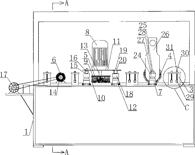
  • Figure 1
    Figure 1
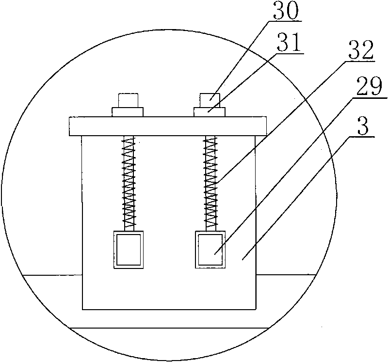
  • Figure 2
    Figure 2
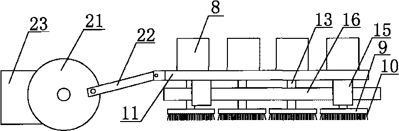
  • Figure 3
    Figure 3
Patent Text Reader

Abstract

The invention discloses a wire drawing machine. Along a wood board transmission direction, the upper end face of a frame is orderly provided with a front steel wire roller which performs rough grinding on wood boards, a disk brush group which performs wire drawing on the wood boards and a rear steel wire roller which polishes the wood boards, wherein the disk brush group consists of a plurality of disk brushes which are distributed abreast; each disk brush is driven to rotate by a respective transmission motor of each disk brush and comprises a disk and steel wires densely distributed on the lower end face of the disk; the disks are all parallel to the upper end face of the frame and are all arranged on a disk brush mounting platform; a disk brush driving motor is fixedly arranged on the disk brush mounting platform; an output shaft of the disk brush driving motor runs through the disk brush mounting platform to be fixedly connected with the disks; and the disk brush group drives the steel wires to rotate through the disks. Compared with the conventional wire drawing machine, in the wire drawing machine of the invention, grooves and lines are widened, which not only increases the contact areas of the steel wires and the surfaces of the wood boards, but also increases a drawing force when the steel wires are contacted with the wood boards, thus the widening of the lines is benefited and the aim of achieving optimal wire drawing effect is achieved.
Need to check novelty before this filing date? Find Prior Art

Description

technical field

[0001] The invention belongs to board processing equipment, in particular to a wood board wire drawing machine with good wire drawing effect. Background technique

[0002] With the improvement of modern people's living standards and the improvement of environmental protection awareness, the requirements for home panel decoration are getting higher and higher. Floors, veneers, door panels and other panels that can only meet the requirements of a single use can no longer meet the needs of the market. Because The disadvantages of traditional decorative panels are that they are basically flat surfaces, and the number of times of paint application is large, and the amount of paint used is large, which not only reduces the environmental quality, but also lacks the natural feeling of solid wood and the three-dimensional effect of wood grain.

[0003] In order to meet the needs of consumers, a kind of brushed floor and veneer with antique relief effect appeared on th...

Examples

Embodiment

[0037] Embodiment: a kind of wire drawing machine, comprises frame 1, is installed with the plank transmission system driven by transmission motor on the end face of frame 1; figure 1 , Figure 4 , Figure 6 As shown, the plank transmission system includes transmission wheels 33 arranged on both sides of the upper end of the frame and transmission belts 34 wrapped around the two transmission wheels 33. The outer surface of the transmission belt 34 is densely covered with grid-like grooves 40 . The transmission wheel 33 is driven to rotate by a transmission wheel motor 35 arranged at the bottom of the frame 1 to control the transmission belt 34 . The two ends of described transmission wheel 33 are installed on the transmission wheel installation block 36, and described transmission wheel installation block 36 lower ends are connected with installation block elevating mechanism, and described installation block elevating mechanism is worm gear transmission mechanism, and it co...