
Tray loading structure for cylindrical workpieces

A technology of cylinders and workpieces, which is applied in the field of production and packaging of cylindrical workpieces, can solve the problems of affecting production efficiency, operator injury, and non-sorting of cylindrical workpieces, and achieves the effect of convenient statistics and analysis and orderly arrangement

Inactive Publication Date: 2010-05-12
CHONGQING UNIV
View PDF0 Cites 3 Cited by
  • Summary
  • Abstract
  • Description
  • Claims
  • Application Information

AI Technical Summary

Problems solved by technology

At present, a fully enclosed and fully automated boating system has been used abroad. The use of this system has greatly improved production efficiency and reduced the damage to the human body caused by cylindrical workpieces during the boating process. The cylindrical workpieces on the metal disk are not sorted or counted, resulting in low efficiency of boat loading, and there is also the phenomenon of cylindrical workpieces falling and blocking
However, the loading process of the production line of radioactive cylindrical workpiece components is still blank in our country. At present, the loading process in China is all manual operation, which not only affects production efficiency, but more importantly, it will cause certain injuries to operators. , poor safety protection, which is extremely inconsistent with the modernization requirements of the related high-tech production industry

Method used


Image

  • Tray loading structure for cylindrical workpieces
  • Tray loading structure for cylindrical workpieces
  • Tray loading structure for cylindrical workpieces

Examples


Embodiment Construction

[0015] The present invention will be further described in detail below with reference to the accompanying drawings and specific embodiments.

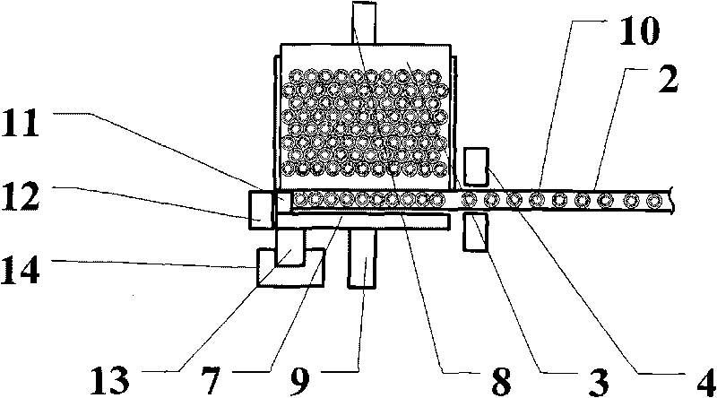
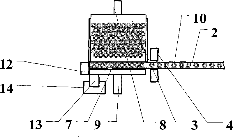
[0016] When implemented, such as Figure 1 to Figure 3 As shown, a plate-loading structure of a cylindrical workpiece is structured as follows: one side of the end of the conveyor belt 2 is horizontally provided with a twitchable pad 3, and the other side is provided with a pusher whose length matches the width of the twitchable pad 3. Rod 7, the upper surface of the movable pad 3 is a smooth plane and one side is connected with a pad pneumatic device 8, the push rod 7 is provided with a push rod pneumatic device 9 on the opposite side of the conveyor belt 2, which pushes When the rod pneumatic device 9 acts, it can drive the push rod 7 to push the cylindrical workpiece 10 above the conveyor belt 2 to the movable backing plate 3; There is a counting device 4; a movable stopper 11 and a fixed stopper 12 are sequentially arranged above t...


PUM


Abstract

The invention discloses a tray loading structure for cylindrical workpieces. One side of a tail end of a cylindrical workpiece conveyor belt is horizontally provided with an extractable subplate, and a push rod of which the length is matched with the width of the extractable subplate is arranged on the other side of the tail end of the cylindrical workpiece conveyor belt; one side of the extractable subplate is connected with a subplate pneumatic device; the other side of the push rod is provided with a push rod pneumatic device; a lateral side of a position before the conveyer belt passes the extractable subplate and the push rod is provided with a counter; a movable check block and a fixed check block are orderly arranged above the tail end of the conveyor belt along the advancing direction; the movable check block is connected with a check block pneumatic device; the check block pneumatic device and the movable check block are integrally arranged on a parallel translating mechanism; and the counter, the check block pneumatic device and the parallel translating mechanism are connected with a control system. The tray loading structure can automatically count and sort the cylindrical workpieces, and can greatly improve boat loading efficiency after the tray loading structure is applied to a boat loading system for the cylindrical workpieces.

Description

technical field [0001] The invention relates to a production and packaging technology for cylindrical workpieces, in particular to a plate-loading structure for cylindrical workpieces. Background technique [0002] At present, the production and packaging of cylindrical workpieces are widely involved in the production of workpieces in the pharmaceutical, food industry and some special industries in my country. For the cylindrical workpiece with radioactivity, in the production process, the cylindrical workpiece pressed by the press must be loaded into a receiving plate in a certain number before entering the next process. This process is called boat loading, in which multiple Catcher plates filled with cylindrical workpieces are overlapped and placed on a metal plate called a boat. At present, a fully enclosed and fully automated boat loading system has been used abroad. The use of this system greatly improves production efficiency and reduces the damage to the human body c...

Claims


Application Information

Patent Timeline
Patent Type & Authority Applications(China)
IPC IPC(8): B65G65/32
Inventor 高潮郭永彩林晓钢扶新
Owner CHONGQING UNIV
Learn More