Conjoined rotary type trash cleaning device

A cleaning machine and rotary technology, which is applied in the cleaning of open water, water conservancy projects, construction, etc., can solve problems such as inability to install and use, and achieve the effects of saving installation space, reliable operation, and reducing costs

Inactive Publication Date: 2010-05-12
QUFU HENGWEI HYDRAULIC MACHINERY
View PDF2 Cites 12 Cited by
  • Summary
  • Abstract
  • Description
  • Claims
  • Application Information

AI Technical Summary

Problems solved by technology

[0003] The purpose of this invention is to overcome the defect that the existing rotary cleaning machine cannot be installed and used under the above conditions. Combined with the trash rack of large-scale hydropower projects, a wide-hole conjoined rotary cleaning machine is designed to be suitable for the above-mentioned processing. Water orifice conditions, solving the problem of cleaning up large-scale hydropower projects

Method used


Image

  • Conjoined rotary type trash cleaning device
  • Conjoined rotary type trash cleaning device
  • Conjoined rotary type trash cleaning device

Examples


Embodiment Construction

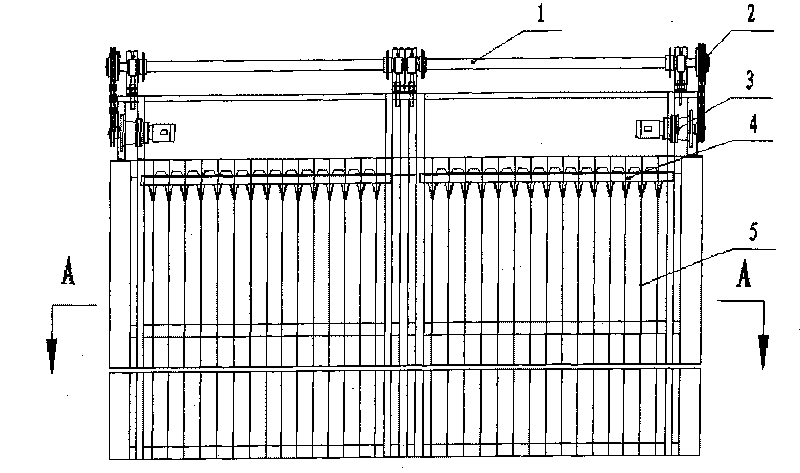
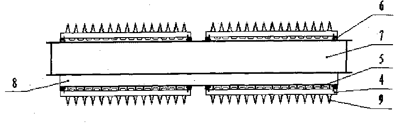
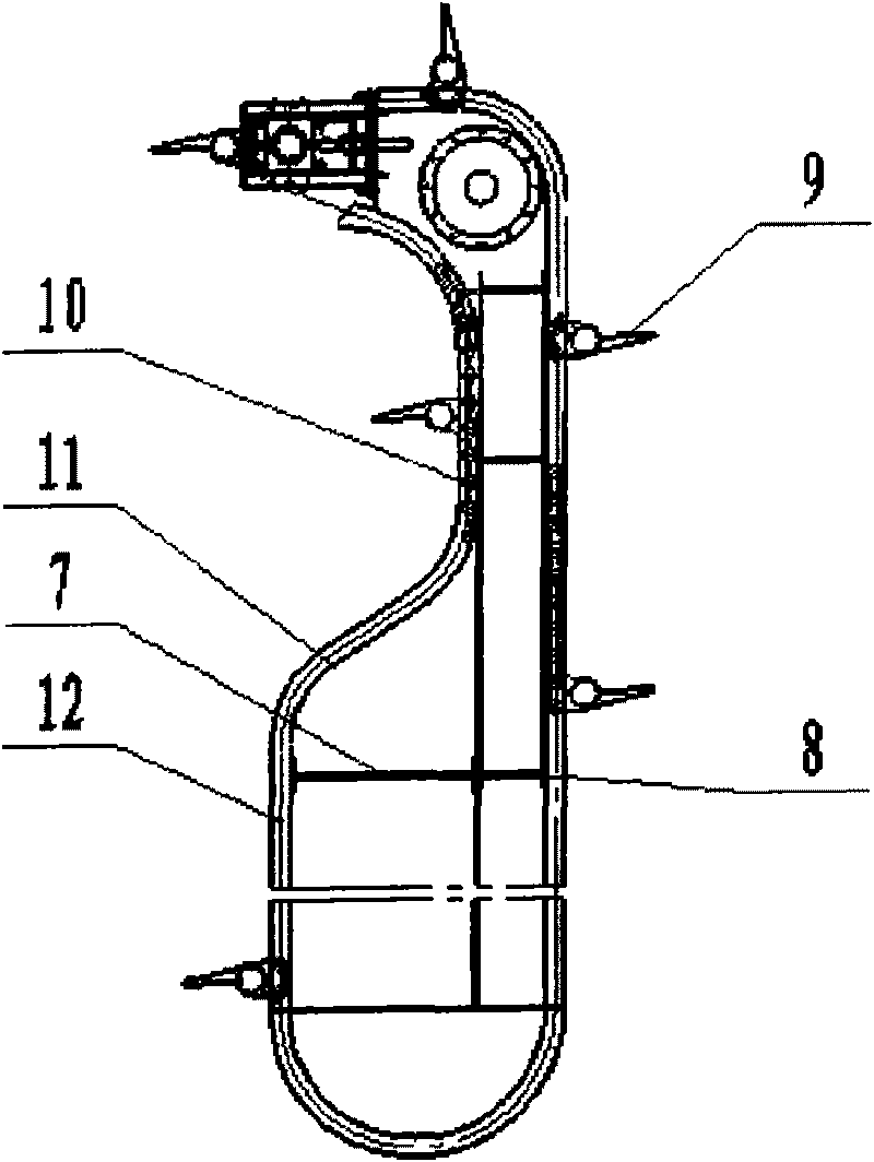
[0020] Combined rotary cleaning machine, including grid body, cleaning tooth rake system, support installation frame, the grid body is composed of vertical grid bars and beams and connected with the support installation frame as a whole, and the cleaning tooth rake system is driven by electric power , and through the supporting drive shaft 1 installed horizontally on the top of the grid body with bearings and bearing seats and the sprocket on it to drive the roller chain 10 to drive the gear rake group that rotates around the grid body, parallel in the horizontal direction of the same set of grid body Set up two sets of symmetrical decontamination rake systems. Each set of decontamination tooth rake systems has a sprocket at both ends of the supporting drive shaft 1, and a pair of chain tracks 6 parallel to the vertical direction are hung on the two sprockets and run around the grid body. The rotating roller chain 10 is equipped with at least one group of horizontally arranged ...


PUM


Abstract

The invention is a hydraulic engineering device, particularly relating to a conjoined rotary type trash cleaning device, comprising a grid body, a trash cleaning tineharrow system and a support erecting frame; the grid body is composed of vertical grids and beams and is connected with the support erecting frame into a whole; the trash cleaning tineharrow system is driven by electrodynamic force and drives a tineharrow set which is transmitted by rolling chains and rotates around the grid body through a support transmission shaft arranged on the top part of the grid body and chain wheels thereon; and at least two sets of trash cleaning tineharrow systems are arranged on the same grid body in parallel along the horizontal direction. The invention has the beneficial effects of big area of drain grating of single device and strong trash cleaning capability, is suitable for water inlet drain grating of large-scale hydraulic engineering with a wide water inlet, and has trash cleaning effect and efficiency which are both superior to the trash cleaning effect and efficiency of each kind of scraper pan type trash cleaning device.

Description

technical field [0001] The invention belongs to water conservancy and hydropower engineering equipment, and is equipment for removing floating objects at water inlets of water conservancy and hydropower engineering, in particular to a conjoined rotary type cleaning machine. Background technique [0002] Rotary cleaning machine is a form of cleaning machine that has been used in water conservancy and hydropower projects for many years and has been gradually expanded. For the main technical structure, see CN 200520139582.8 and CN02255239.1 barrier-free rotary cleaning machine. However, due to its structural strength and other reasons, it has not been applied in large-scale hydropower engineering projects. Inlet orifice conditions in large-scale hydropower projects: width 6-12 meters, water head difference greater than 4 meters, flow velocity greater than 3 meters per second, interception depth greater than 18 meters, such as the Yangtze River, the Yellow River and other major...

Claims


Application Information

Patent Timeline
Patent Type & Authority Applications(China)
IPC IPC(8): E02B15/10E02B15/06
Inventor 吴祥海王建辉张少卿翟常伟孔庆利戴雷倪
Owner QUFU HENGWEI HYDRAULIC MACHINERY
Why Eureka
Try Eureka