
Technology and device for cooling and purifying high-temperature and high-pressure biomass synthesis gas

A technology of high temperature and high pressure, purification process, applied in combustible gas purification, combustible gas purification/transformation, chemical industry, etc., can solve the problem of inability to achieve biomass synthesis gas cooling effect and purification indicators, poor stability and economy, complex system, etc. problems, to achieve the effect of reducing energy consumption, reducing possibilities, and solving complex systems

Active Publication Date: 2013-08-28
WUHAN KAIDI ENG TECH RES INST CO LTD
View PDF4 Cites 9 Cited by
  • Summary
  • Abstract
  • Description
  • Claims
  • Application Information

AI Technical Summary

Problems solved by technology

The temperature of the crude gas coming out of the carbonization chamber is about 650°C, and the temperature of the syngas at the outlet of the biomass gasifier is higher than the temperature of the gas at the outlet of the carbonization chamber. In the specific situation of high flue gas temperature, it is obvious that the cooling effect and purification index of biomass syngas cannot be achieved by copying the process method of initial cooling of coal gas.
Moreover, if the traditional coal-to-gas purification method is simply simulated, there are still defects such as complex system, long process, high energy consumption, low efficiency, poor stability and economy

Method used


Image

  • Technology and device for cooling and purifying high-temperature and high-pressure biomass synthesis gas

Examples


Embodiment Construction

[0028] The present invention will be further described below in conjunction with the accompanying drawings and specific embodiments, but the present invention is not limited to the following embodiments.

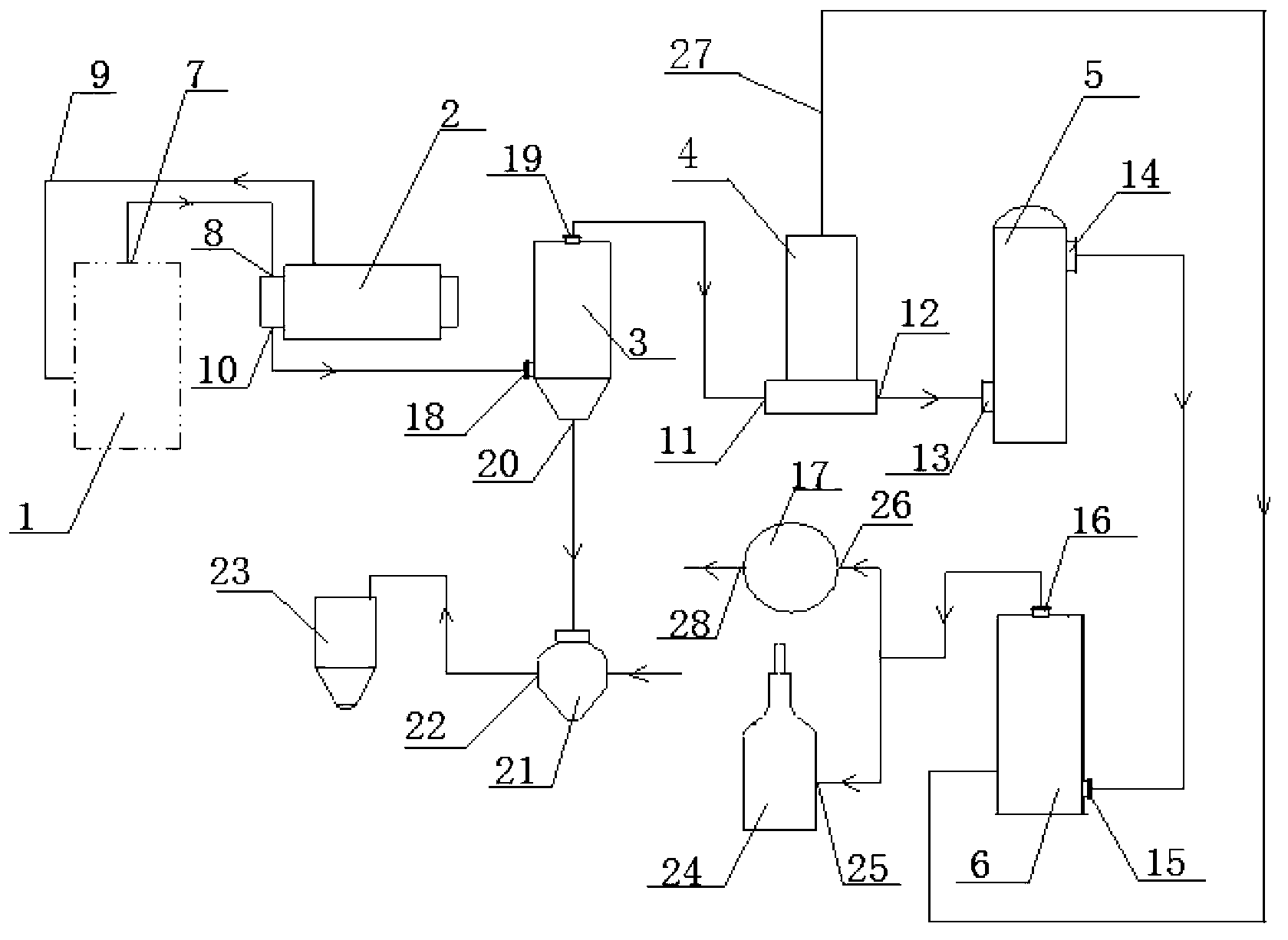
[0029] figure 1The high-temperature and high-pressure biomass synthesis gas cooling and purification equipment shown in , including shell-and-tube waste heat boiler 2 and vertical flue tube waste heat boiler 4 for cooling biomass synthesis gas, and Venturi scrubbing for purification of biomass synthesis gas The tower 5 and the wet electrostatic precipitator 6, the dry gas filter 3 is arranged between the shell-and-tube waste heat boiler 2 and the vertical flue-tube waste heat boiler 4, the air inlet 8 of the shell-and-tube waste heat boiler 2 is connected with the biomass gasification The synthesis gas outlet 7 of the furnace 1 is connected, the gas outlet 10 of the shell-and-tube waste heat boiler 2 is connected with the air inlet 18 at the lower end of the dry gas filter 3...


PUM


Abstract

The invention discloses a technology and device for cooling and purifying high-temperature and high-pressure biomass synthesis gas. The technology comprises the following steps of: (1) subsection cooling, namely cooling the high-temperature and high-pressure biomass synthesis gas coming out of a biomass gasifier to 350-550 DEG C by process water, recovering waste heat to produce medium-pressure steam, and after that, cooling the biomass synthesis gas to 100-300 DEG C, and recovering waste heat to produce low-pressure steam; (2) collecting and removing tar; (3) washing and purifying; and (4) treating the biomass synthesis gas by a wet type electrostatic precipitator, wherein the pressure of the treated biomass synthesis gas is 0.1-1 MPa. The device mainly comprises a tube shell type waste heat boiler, a dry-type gas filter, a vertical smoke tube waste heat boiler, a packless venturi scrubbing tower and the wet type electrostatic precipitator. The technology and the device can be used for controlling appropriate technological parameters by the optimal design of the technical scheme, thus realizing subsection cooling of the biomass synthesis gas, cascade recycling of the waste heat, gradual dust removal and the purification target of tar removal. The technology and the device are simple in equipment, smooth in technology, low in energy consumption, high in efficiency, high in safety and stability and good in economic benefit.

Description

technical field [0001] The invention relates to synthesis gas purification technology, in particular to a high-temperature and high-pressure biomass synthesis gas cooling and purification process and equipment thereof. Background technique [0002] In the field of energy utilization, the reserves of the most commonly used non-renewable resources such as oil, coal, and natural gas have declined sharply due to massive exploitation, which has constituted one of the three major crises that endanger human survival and development. However, in the rural areas of our country, a large amount of straw, straw, chaff, corn stalks, cotton stalks, rape stalks, peanut shells and other straws are discarded or burned every year, seriously polluting the environment. Therefore, the biomass gasification technology that utilizes these biomass energy sources has emerged as the times require. The development and utilization of biomass renewable and clean energy has attracted increasing attention ...

Claims


Application Information

Patent Timeline
Patent Type & Authority Applications(China)
IPC IPC(8): C10K1/04C10K1/02C10K1/10
CPCC10K1/028C10K1/04Y02P20/10Y02P20/129
Inventor 张岩丰聂洪涛夏明贵刘文焱张亮
Owner WUHAN KAIDI ENG TECH RES INST CO LTD
Learn More