
Light-focusing module and backlight module

A light, light-emitting surface technology, applied in optics, optical components, nonlinear optics, etc., can solve the problem of liquid crystal display devices not passing through

Active Publication Date: 2011-10-19
KUSN INFOVISION OPTOELECTRONICS
View PDF7 Cites 0 Cited by
  • Summary
  • Abstract
  • Description
  • Claims
  • Application Information

AI Technical Summary

Problems solved by technology

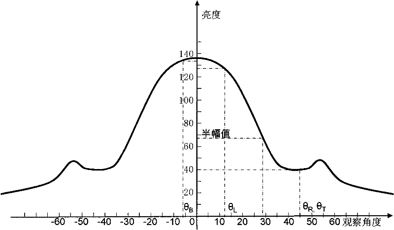
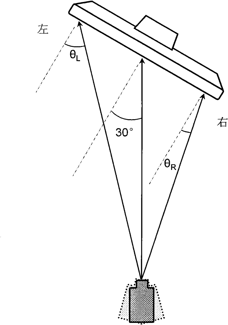
According to the foregoing, the luminance ratio (P R / P L ) is 128 / 40=3.20, therefore, adopt figure 2 The liquid crystal display device with a prism sheet whose luminance half-width angle is about 28 degrees cannot pass the test according to the requirements of the TCO99, 2003 standard

Method used


Image

  • Light-focusing module and backlight module
  • Light-focusing module and backlight module
  • Light-focusing module and backlight module

Examples


Embodiment Construction

[0047] In order to make the above objects, features and advantages more comprehensible, specific implementations of the present invention will be described in detail below in conjunction with the accompanying drawings.

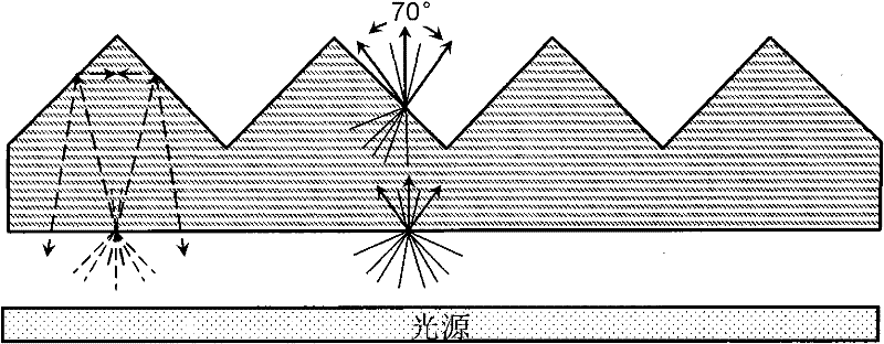
[0048] refer to Figure 5 , which is a schematic diagram of an exploded structure of the backlight module 100 according to an embodiment of the present invention. For the convenience of description, it is assumed that the backlight module 100 is placed horizontally. The backlight module 100 includes a backplane 1 , a reflector 2 , a light guide panel (LGP: Light Guide Panel) 3 , a lower diffuser 4 , a light collecting module 5 , an upper diffuser 6 and a light tube 7 . Wherein, the lamp tube 7 is arranged on the back plate 1, and it can be a direct type or a side type. The lamp tube 7 is a line light source, such as a cold cathode fluorescent lamp (CCFL: Cold Cathode Fluorescent Lamp). The light guide plate 3 converts the line light source emitted by the lam...


PUM


Abstract

The invention provides a light-focusing module and a backlight module using the light-focusing module. The light-focusing module comprises a light emitting face and a plurality of light-focusing microstructures; the light emitting face has a geometric center; the light of each light-focusing microstructure has the maximum emitting brightness in certain direction; when the inclined angle between the light emitting direction and the certain direction is a brilliance semi-range angle, the brightness decreases to half the maximum emitting brightness; the light-focusing microstructures change gradually from the geometric center of the light emitting face towards the direction far away from the geometric center, the farer from the geometric center of the light emitting face, the larger the brilliance semi-range angle of the light-focusing microstructures. A liquid crystal display using the light-focusing module and the backlight module seems to have more uniform brightness.

Description

【Technical field】 [0001] The invention relates to the field of liquid crystal display, in particular to a backlight module and a light-gathering module used for a liquid crystal display device. 【Background technique】 [0002] Liquid Crystal Display (LCD) has many advantages such as lightness, lightness, energy saving, and no radiation, so it has gradually replaced the traditional cathode ray tube (CRT) display. Currently, liquid crystal display devices are widely used in electronic equipment such as high-definition digital televisions, desktop computers, personal digital assistants (PDAs), notebook computers, mobile phones, and digital cameras. [0003] Anyone who has used a notebook computer or an LCD desktop monitor will find that the display screen has a certain viewing angle, that is, when the computer or monitor is observed from a direction perpendicular to the display plane (that is, the normal direction), the brightness (also known as "brightness" in the industry) is ...

Claims


Application Information

Patent Timeline
Patent Type & Authority Patents(China)
IPC IPC(8): G02F1/13357F21V5/00G02B5/00
Inventor 赖信杰陈世宪
Owner KUSN INFOVISION OPTOELECTRONICS
Learn More