Motor, terminal device and method for heat dissipation of terminal

A technology of motors and terminals, which is applied in the field of communication, can solve the problem that the internal devices of the terminal cannot be thermally radiated and interfered with, and achieve the effect of reducing the interference of thermal radiation on the devices

Inactive Publication Date: 2010-05-12
ZTE CORP
View PDF0 Cites 9 Cited by
  • Summary
  • Abstract
  • Description
  • Claims
  • Application Information

AI Technical Summary

Problems solved by technology

[0005] The present invention provides a motor terminal device and a method for dissipating heat from the terminal, so as to solve the problem of ther

Method used


Image

  • Motor, terminal device and method for heat dissipation of terminal
  • Motor, terminal device and method for heat dissipation of terminal
  • Motor, terminal device and method for heat dissipation of terminal

Examples


Embodiment 1

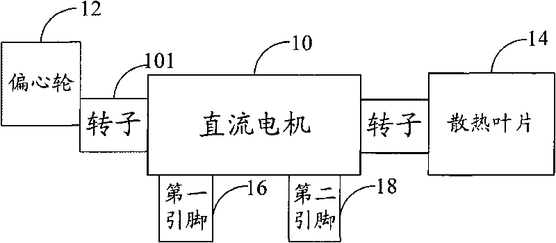
[0049] According to an embodiment of the present invention, a motor is provided, which is disposed on a terminal, figure 1 It is a structural schematic diagram of the motor of Embodiment 1 of the device of the present invention, such as figure 1 As shown, the motor according to the embodiment of the present invention includes: a DC motor 10 composed of a rotor 101 and a coil (not shown in the figure), an eccentric wheel 12 arranged at one end of the rotor 101, and a cooling blade 14 arranged at the other end of the rotor 101 , and the first pin 16 provided on the DC motor 10 . Next, the motor of Embodiment 1 of the device of the present invention will be described in detail.

[0050] Specifically, the eccentric wheel 12 arranged at one end of the rotor 101 can cause the motor to vibrate under the drive of the rotor 101 through the DC motor 10; vibration. Among them, the high-speed rotating DC motor provides the original power, and the embodiment of the present invention uti...

Embodiment 2

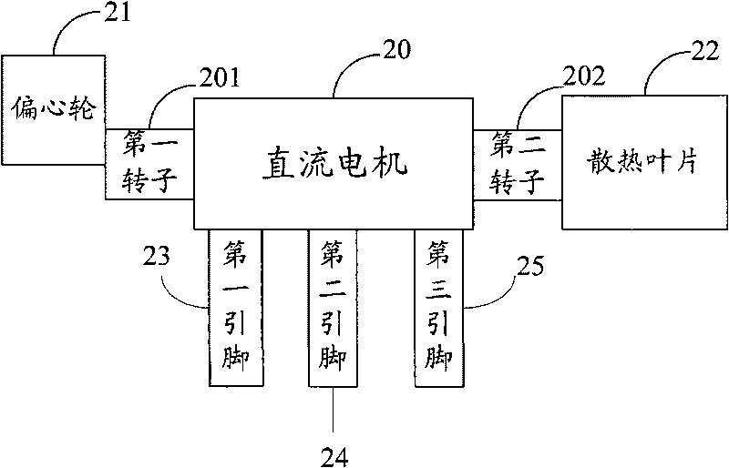
[0055] According to an embodiment of the present invention, a motor is provided, which is disposed on a terminal, figure 2 It is a structural schematic diagram of the motor of the second embodiment of the device of the present invention, such as figure 2 As shown, the motor according to the embodiment of the present invention includes: a DC motor 20 composed of a first rotor 201, a second rotor 202, and a coil (not shown in the figure), an eccentric wheel 21 connected to the first rotor 201, a connection To the cooling fins 22 of the second rotor 202 , the analog switch (not shown), the first pin 23 provided on the DC motor 20 , and the second pin 24 provided on the DC motor 20 . Next, the motor of the embodiment of the present invention will be described in detail.

[0056] The embodiments of the present invention independently control the vibration and heat dissipation of the motor. Inside the motor, using the same coil, two rotors 201 and 202 are respectively connected ...

Embodiment 3

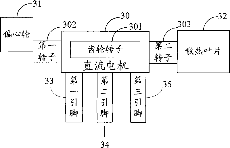
[0067] According to an embodiment of the present invention, a motor is provided, which is disposed on a terminal, image 3 It is a structural schematic diagram of the motor of the third embodiment of the device of the present invention, as image 3 As shown, the motor according to the embodiment of the present invention includes: a DC motor 30 composed of a gear rotor 301 and a coil (not shown in the figure), a first driving wheel 302 connected to the gear rotor 301, and a second driving wheel 303, The eccentric wheel 31 connected to the first driving wheel 302, the cooling blade 32 connected to the second driving wheel 303, the first pin 33 arranged on the DC motor 30, and the second pin 34 arranged on the DC motor 30 . Next, the motor of the embodiment of the present invention will be described in detail.

[0068] The embodiment of the present invention achieves the purpose of separately controlling the heat dissipation function and the vibration function of the motor throu...


PUM


Abstract

The invention discloses a motor, a terminal device and a method for heat dissipation of terminal, wherein the motor is arranged in the terminal; the motor comprises a direct current machine which is composed of a rotor and a coil, an eccentric wheel, a heat dissipation blade and a first lead foot, wherein the eccentric wheel is arranged at one end of the rotor and is used for leading the vibration of the motor under the driving of the rotor through the direct current machine; the heat dissipation blade is arranged at the other end of the rotor and is used for moving for heat dissipation under the driving of the rotor through the direct current machine when the motor vibrates; and the first lead foot is arranged on the direct current machine and is used for connecting the power supply which supplies power for the direct current machine. The technical scheme of the invention can reduce the interference of heat radiation on the equipment and the body damage of users.

Description

technical field [0001] The present invention relates to the communication field, and in particular to a method for dissipating heat from a motor, a terminal device and a terminal. Background technique [0002] At present, as the functions of the terminal increase, the power consumption required by the terminal also increases accordingly. In the application of the terminal, the radio frequency power amplifier device used in the call, the audio power amplifier device for playing audio and video, and the central processing unit (Central Processing Unit, referred to as CPU) will emit a lot of heat when they work for a long time. The structure is relatively small, so that the devices in the terminal are placed in a concentrated manner, resulting in poor heat dissipation of the terminal, which greatly affects the use of users. In addition, a large amount of heat radiation emitted by the terminal will also cause certain harm to the human body. Therefore, the heat dissipation of t...

Claims


Application Information

Patent Timeline
IPC IPC(8): H02K7/075H02K9/06H02K16/02H04M1/02H04M1/725
Inventor 贾庆辉佘海波赵恺戚跃升胡卫东
Owner ZTE CORP
Why Eureka
Try Eureka