DSP based Ethernet communication method in fault recording system

A technology of fault recording and communication method, which is applied in the field of Ethernet communication, can solve the problem of large data volume and achieve the effect of small memory capacity

Active Publication Date: 2010-05-12
NANJING GUODIAN NANZI POWER GRID AUTOMATION CO LTD
View PDF0 Cites 11 Cited by
  • Summary
  • Abstract
  • Description
  • Claims
  • Application Information

AI Technical Summary

Problems solved by technology

In addition, due to the strong real-time nature and large amou

Method used


Image

  • DSP based Ethernet communication method in fault recording system
  • DSP based Ethernet communication method in fault recording system
  • DSP based Ethernet communication method in fault recording system

Examples


Embodiment Construction

[0052] The present invention will be further described below in conjunction with the accompanying drawings.

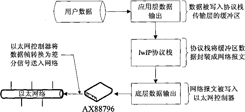
[0053] figure 1 It is a flow chart of network data input in the DSP system in the present invention. The input process of network data among the present invention is:

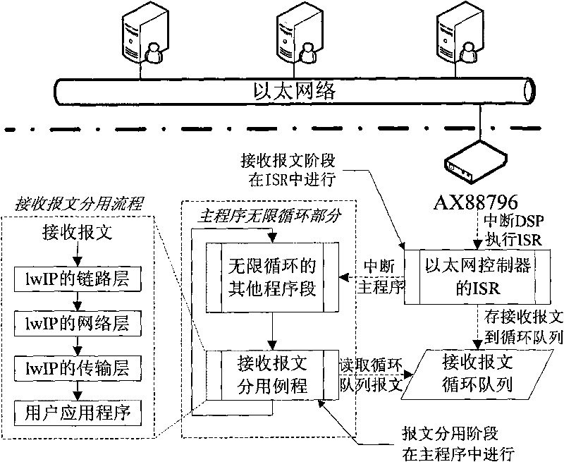
[0054]The input of network data is usually initiated by the receiving message interrupt of the Ethernet controller, and the DSP will read all new message data from the Ethernet controller after receiving the interrupt. The received message must go through the TCP / IP protocol stack demultiplexing (Demultiplexing), and gradually parsed before being transmitted to the user application layer.

[0055] In the DSP main control system, the input of network data is divided into two stages: the stage of receiving and receiving messages by the Ethernet driver and the stage of dividing the received messages by the protocol stack.

[0056] In the receiving message interrupt service program, the Ethernet driver s...


PUM


Abstract

The invention discloses a DSP based Ethernet communication method in a fault recording system, comprising the following steps of: (1) after a message interrupt service routine is received, storing received messages into Pbufs chain buffers, also sequentially storing pointers of the chain buffers storing the messages into a self-defined received message circulating array without directly transmitting to a protocol stack, when the messages are completely received, interrupting the service routine, i.e. quitting; (2) transmitting the messages inside the circulating array to a 1wIP protocol stack for demultiplex; (3) inputting application layer data; (4) outputting the application layer data; (5) encapsulating the messages written into a buffering area of a transmission layer of the protocol stack into network messages; (6) writing the network messages into an Ethernet controller, and transforming data frames into differential signals to be transmitted to a network by the Ethernet controller. The DSP based Ethernet communication method in the fault recording system can realize that the data information of the fault recording system is fast communicated through the Ethernet.

Description

technical field [0001] The invention relates to a DSP-based Ethernet communication method in a fault recording system, belonging to the technical field of electricity and communication. Background technique [0002] In the fault recording system, due to the large amount of data, the data transmission is carried out through the traditional network, the network expansion speed is low, the real-time performance is poor, and the TCP / IP protocol is not supported. [0003] TCP / IP Ethernet communication is now becoming the most important means of communication, and DSP embedded design has also penetrated into many fields of industrial control. Combining the two and utilizing existing network resources to realize high-speed DSP Ethernet communication needs to be solved The following questions: [0004] 1) If DSP wants to expand high-speed Ethernet, it must select a good Ethernet controller; [0005] 2) Write or transplant TCP / IP protocol stack; [0006] 3) To write a network driv...

Claims


Application Information

Patent Timeline
IPC IPC(8): H04L29/06H04L12/28G01R31/08
Inventor 戴超金
Owner NANJING GUODIAN NANZI POWER GRID AUTOMATION CO LTD
Why Eureka
Try Eureka