Sliding nozzle device

A sliding nozzle and pulley technology, which is used in casting melt containers, metal processing equipment, casting equipment, etc., can solve problems such as many operating errors and mistakes, unreasonable operating mechanisms, and inaccurate control, and achieve cost reduction and structure simplification. , control the precise effect

Active Publication Date: 2010-05-19
HENAN RONGJIN HIGH TEMPERATRUE MATERIALS CO LTD
View PDF0 Cites 4 Cited by
  • Summary
  • Abstract
  • Description
  • Claims
  • Application Information

AI Technical Summary

Problems solved by technology

[0004] Most of the existing water slide devices have insufficient optimization of the interior design of the slide brick chamber, resulting in high cost of refractory materials. In addition, there is often a water hole sleeve at the installation position of the water hole and the block, which is used to assist in the installation of the water hole and provide a guarantee for the entire device. A lot of cost has been increased. In addition, the original operating mechanism is not reasonable enough, the control is not precise enough, there are many operating errors and errors, and the operation is laborious.

Method used


Image

  • Sliding nozzle device
  • Sliding nozzle device
  • Sliding nozzle device

Examples


Embodiment

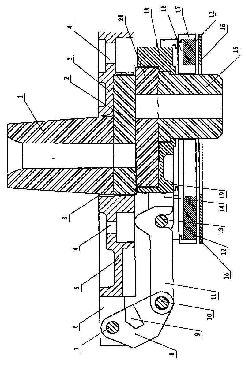
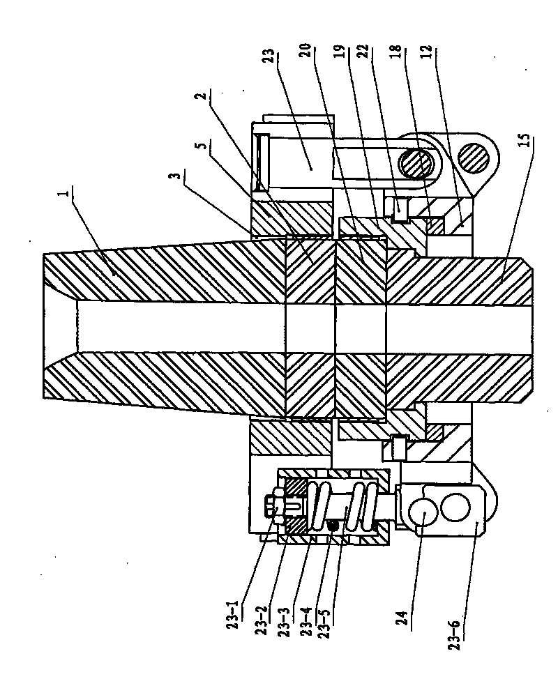
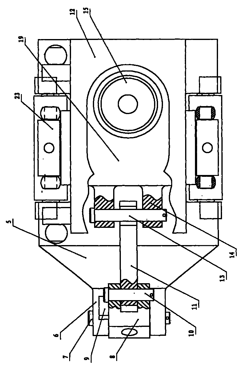
[0030] Example: see Figure 1-Figure 10 , in the figure 1. Upper nozzle, 2. Upper slide brick, 3. Upper nozzle hole, 4. Mounting hole, 5. Base, 6. Hinged ear A, 7. Hinged shaft A, 8. Rocker arm, 9. Limit Block, 10. Winged shaft B, 11. Hook bar, 12. Sliding bracket, 13. Cross bar, 14. Hinged ear B, 15. Water outlet, 16. Protective plate, 17. Compression bar, 18. Slider, 19. pulley, 20. sliding plate brick, 22. sliding pin, 23, spring locking mechanism, 24. pressing shaft.

[0031] Among them, 23-1. Compression nut, 23-2. Press plate, 23-3. Spring box, 23-4. Spring, 23-5. Pull rod, 23-6. Compression elbow, 19-1. Lower plate brick cavity , 19-2. Step snap ring, 19-3. Drain installation hole, 19-4. Chute, 8-1. Operating hole, 8-2. Hinged hole, 8-3. Hinged hole, 9-1 . Limiting surface.

[0032] A sliding nozzle device, including a base 5, a sliding brick and a sliding bracket 12, a pulley 19 is provided between the base 6 and the sliding bracket 12, and a spring locking mechanis...


PUM


Abstract

The invention relates to a sliding nozzle device which comprises a pedestal, sliding plate bricks and a sliding support, wherein a pulley is arranged between the pedestal and the sliding support, a spring locking mechanism is respectively arranged at both outer sides of the pedestal and the sliding support, a link mechanism formed by a rocking arm and a hook bar is respectively hinged at one end part of the pedestal and the sliding support, an upper sliding plate brick chamber is arranged in the middle on the lower surface of the pedestal, an upper sliding plate brick is installed in the chamber, a through hole is arranged at the upper part of the chamber, an upper nozzle is installed at the upper part of the chamber, a lower sliding plate brick chamber is arranged in the middle on the upper surface of the pulley, a lower sliding plate brick is installed in the chamber, a lower nozzle mounting hole is arranged at the lower part of the chamber of the pulley, a step type snap ring is arranged on the inner edge of the hole, and a lower nozzle with steps is installed in the lower nozzle mounting hole; the chambers for installing the upper sliding plate brick and the lower sliding plate brick inside the pedestal and the pulley are both oblong chambers respectively provided with a small circular arc at one end and a large circular arc at one end, and the large circular arc and the small circular arc are in tangent transitional connection; and the device has lower cost, convenient operation and accurate control, and is very beneficial to popularization and application.

Description

1. Technical field [0001] The invention relates to a flow-limiting device for controlling the discharge of molten steel from a ladle, in particular to a sliding nozzle device used on a ladle. 2. Background technology [0002] The sliding nozzle device is the equipment that must be used in steelmaking production, and its function is to flow out the molten steel in the ladle through the sliding nozzle for pouring. The sliding nozzle mainly includes the upper nozzle and the lower nozzle, and the upper and lower sliding bricks connected to the upper and lower nozzles respectively. The sliding of the sliding bricks connects the upper and lower nozzles, and controls the molten steel in the ladle to flow out through the sliding nozzle for pouring. [0003] At present, the sliding nozzle device commonly used by people generally consists of a mounting plate, an upper sliding plate, a lower plate, a supporting plate, a frame, a connecting plate, a spring box, a spring, and a locking b...

Claims


Application Information

Patent Timeline
Patent Type & Authority Applications(China)
IPC IPC(8): B22D41/22
Inventor 徐林富徐跃庆李宏宇徐跃刚梁保青徐光雷左晓东刘忠森
Owner HENAN RONGJIN HIGH TEMPERATRUE MATERIALS CO LTD
Why Eureka
Try Eureka