Method for manufacturing guide groove of servomotor cylinder of runner cone of hydroturbine

A relay cylinder and drain cone technology, applied in metal processing equipment, manufacturing tools, details of milling machine equipment, etc., can solve the problems of easy deformation of workpieces, increased labor costs, poor operability of workers, etc., and achieve low processing costs, The effect of easy operation, improved machining accuracy and production efficiency

Inactive Publication Date: 2010-05-19
TIANJIN TIRNFR HEAVY HYDROELECTRIC FRCILITY CO LTD
View PDF0 Cites 1 Cited by
  • Summary
  • Abstract
  • Description
  • Claims
  • Application Information

AI Technical Summary

Problems solved by technology

Problems existing in traditional processing technology: (1) Repeated welding and removal of the support frame makes the workpiece easily deformed, so it is difficult to guarantee the machining accuracy; (2) The welded support frame only plays a supporting role, and the position of the support frame does not change. It is not fixed, therefore, it is difficult to align the drain cone (workpiece), and the operability of the workers is poor; (3) only one guide groove can be processed because of each welding of the support frame; if the drain cone has two guide grooves , the support frame needs to be welded twice, and the support frame needs to be removed once; at the same time, the workpiece needs to be aligned twice; resulting in repeated man-hours; and usually the drain cone has three guide grooves, the man-hours are repeated three times, which greatly increases Hours of work
[0005] Based on the above analysis, the main problem in the processing of the drain cone is its shape. The conical shape makes it difficult to clamp and align the workpiece.

Method used


Image

  • Method for manufacturing guide groove of servomotor cylinder of runner cone of hydroturbine
  • Method for manufacturing guide groove of servomotor cylinder of runner cone of hydroturbine
  • Method for manufacturing guide groove of servomotor cylinder of runner cone of hydroturbine

Examples


Embodiment Construction

[0016] In order to further understand the invention content, characteristics and effects of the present invention, the following examples are given, and detailed descriptions are as follows in conjunction with the accompanying drawings:

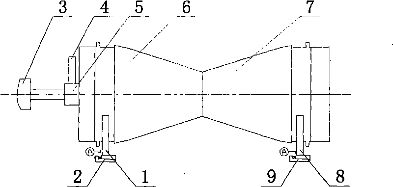
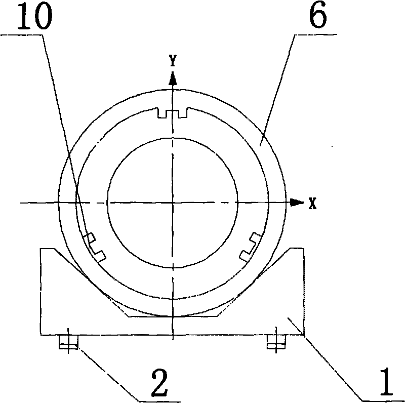
[0017] Such as figure 1 , figure 2 As shown, two V-shaped irons 1, 8 are installed on the boring machine workbench, and adjusting pad irons 2, 9 are installed below the two V-shaped irons. The water discharge cone is horizontally placed on the V-shaped iron, and the water discharge cone is the water discharge cone 6, 7 with two small ends butted. After aligning the drain cone with the boring machine main shaft 3, fix it, install the right-angle milling head 5 on the boring machine main shaft, and install the end mill 4 on the milling head to process the guide groove 10. The drain cone guide groove 10 is made according to the following process steps:

[0018] (1) Align the small ends of the two water discharge cones first, and spot weld t...


PUM


Abstract

The invention relates to a method for manufacturing a guide groove of a servomotor cylinder of a runner cone of a hydroturbine. The method is characterized in that a boring lathe workbench is provided with two V-shaped irons; a regulating parallel is arranged under each V-shaped iron; small ends of two runner cones are aligned with each other and firmly welded by a butt strap; then, the two runner cones are arranged on the V-shaped irons horizontally, and are fixed after being aligned with a principal axis of a boring lathe in each direction; the principal axis of the boring lathe is provided with a right-angle milling head; and the milling head is provided with an end mill manufacturing guide groove. The method solves the problems of difficult assembly and difficult alignment in manufacturing the guide groove of the runner cones, greatly improves the manufacture accuracy and production efficiency, and has the advantages of easy operation and low manufacture cost.

Description

technical field [0001] The invention relates to a method for processing a guide groove of a cylinder of a water discharge cone servomotor of a water turbine runner. Background technique [0002] The "discharge cone" is one of the key parts in the "runner assembly" of the hydroelectric generator set. It is a conical rotary welded part. There are three guide grooves on the inner wall of the large end of the cone. Its function is to make the "servoster The guide key on the "cylinder" reciprocates along the guide groove, so that the "connecting rod" and "rotary arm" form a linkage mechanism, and finally drive the "blade" to open and close. [0003] The requirements for the guide groove of the drain cone are very strict. In addition to the dimensional accuracy of each guide groove, there are also requirements for the position of each guide groove. The traditional processing method is: the drain cone is arranged on the BSF-Φ130 CNC boring machine , After the large end of the drai...

Claims


Application Information

Patent Timeline
IPC IPC(8): B23C3/30
Inventor 王建
Owner TIANJIN TIRNFR HEAVY HYDROELECTRIC FRCILITY CO LTD
Why Eureka
Try Eureka