
Crystal ball face milling machine

A crystal ball and surface grinding machine technology, which is applied in the direction of spherical grinders, grinding machines, grinding/polishing equipment, etc., can solve the problem that the crystal blank clamping mechanism cannot change the relative position according to the processing requirements, and the positioning and clamping of the aluminum row is time-consuming and laborious. The range of the ball grinding surface becomes smaller, etc., to achieve the effect of increasing the grinding surface rotation angle range, simple structure, and solving insufficient torque

Inactive Publication Date: 2011-04-06
浙江博联智能科技有限公司
View PDF2 Cites 0 Cited by
  • Summary
  • Abstract
  • Description
  • Claims
  • Application Information

AI Technical Summary

Problems solved by technology

[0005] The present invention mainly provides a kind of exquisite structure, ingenious conception, automatic positioning and clamping when the aluminum row is clamped, and two sets of crystal blank clamping mechanisms can independently and accurately position and move relative to the grinding disc mechanism along the horizontal or vertical direction, thereby The surface grinding range of the crystal ball is increased, which effectively improves the production efficiency and precision of the crystal ball grinding machine, and solves the time-consuming and laborious process of positioning and clamping the aluminum row in the prior art, and the clamping mechanism of the crystal blank cannot be changed according to the processing requirements. Its relative position to the grinding disc makes the scope of the crystal ball grinding surface smaller and the production efficiency is low.

Method used


Image

  • Crystal ball face milling machine
  • Crystal ball face milling machine
  • Crystal ball face milling machine

Examples


Embodiment

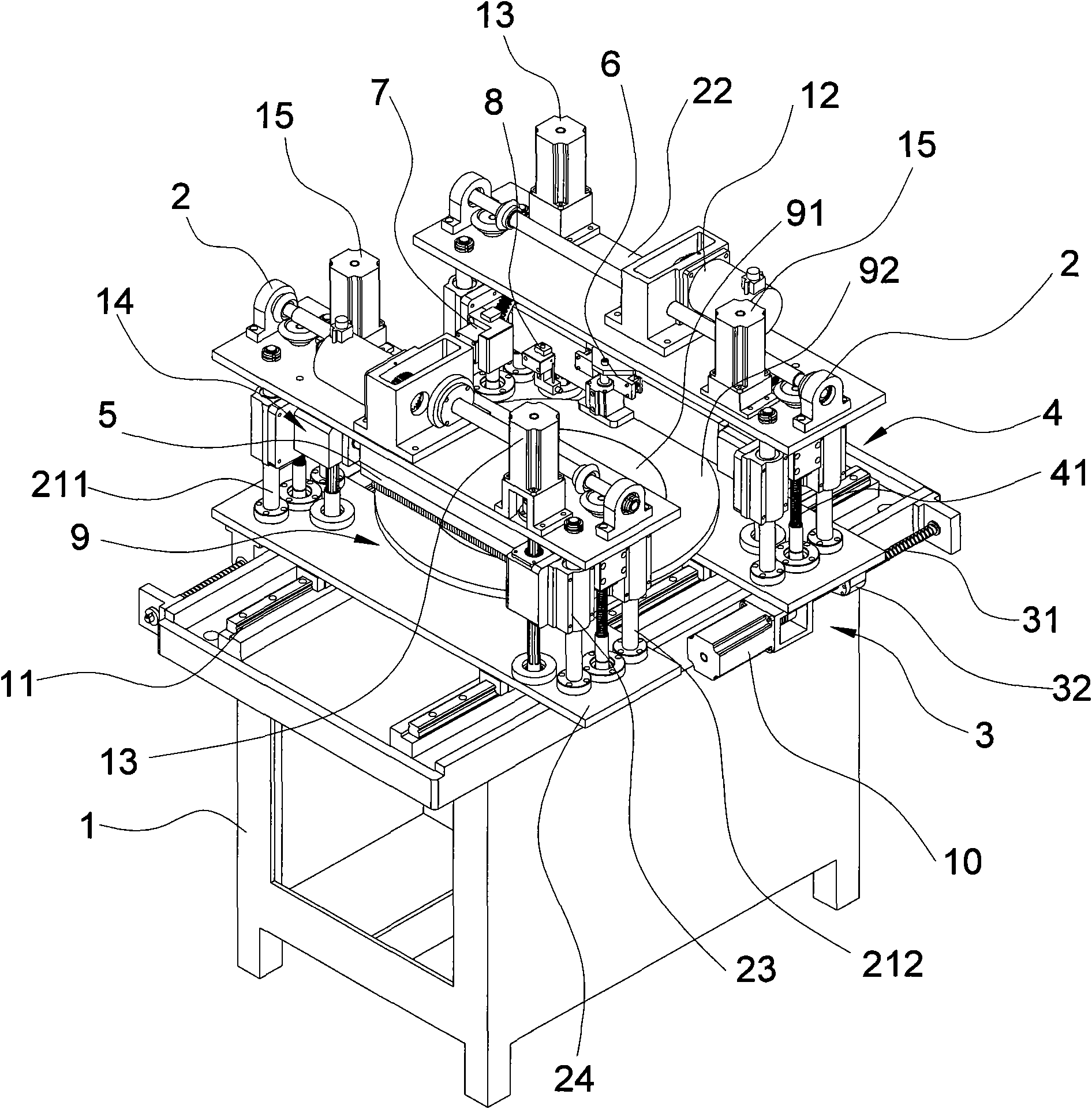
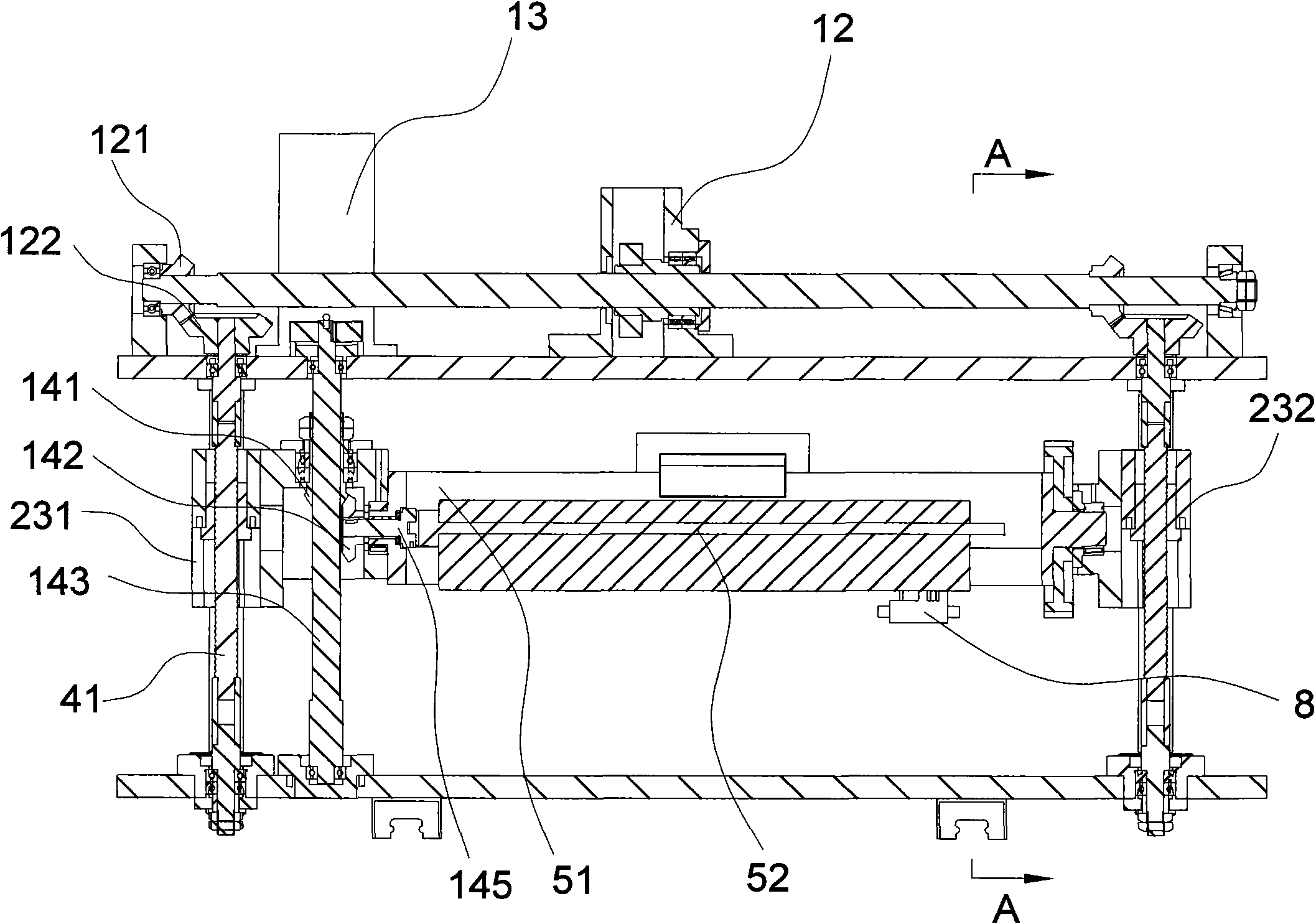
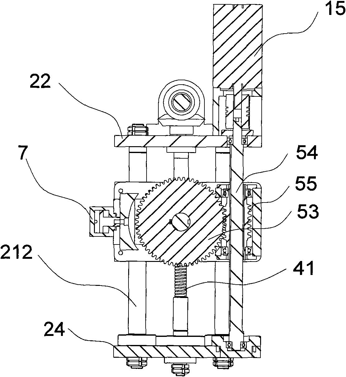
[0026] Such as figure 1 with figure 2 Shown, a kind of crystal ball noodle grinding machine of the present invention comprises frame 1 and the disc mechanism 9 that is located on frame 1, and is located on frame 1 and can slide horizontally along slide rail 11 on frame 1 and A pair of center-symmetrically distributed bracket mechanisms 2 matched with the grinding disc mechanism 9 are fixed with aluminum rows 5 through movable dovetail groove clamps 6 that are automatically clamped on the bracket mechanism 2, and corresponding to the drag brackets on the frame 1. The rack mechanism 2 is provided with two horizontal moving mechanisms 3, and the horizontal moving mechanism 3 can make the corresponding carriage mechanism 2 move along the horizontal direction independently on the frame 1, and the vertical moving vertical direction is provided on the carriage mechanism 2. Straight moving mechanism4. The carriage mechanism 2 comprises a left cylinder guide rail 211 and a right cyl...


PUM


Abstract

The invention discloses a crystal ball face milling machine, which has a unique structure, is skillfully designed, can automatically position and clamp aluminum bar in aluminum assembly, allows a bracket towing mechanism to independently and accurately position and move along a horizontal or vertical direction relative to a milling disc mechanism, effectively improves production efficiency and accuracy. The invention solves a technical problems existing in the prior art that the positioning-clamping process of the aluminum bars is time consuming and labor consuming and the bracket towing mechanism cannot change the positions relative to the milling disc according to processing requirements, so that the face-milling range of the crystal ball becomes smaller and the production efficiency islow. The crystal ball face milling machine comprises a machine frame, a milling disc mechanism arranged on the machine frame and a pair of bracket towing mechanisms which horizontally slide along slide rails on the machine frame and are arranged on the machine frame and matched with the milling disc mechanism, wherein the bracket towing mechanisms are fixedly provided with the aluminum bars; the machine frame is provided with a mechanism which can make each bracket towing mechanism independently move on the machine frame along the horizontal or vertical direction; and the aluminum bars are fixed on the bracket towing mechanisms by movable type dovetail groove clamps.

Description

technical field [0001] The invention relates to a crystal workpiece processing equipment, in particular to a crystal ball noodle grinder. Background technique [0002] Existing crystal flour milling machine comprises frame, drag frame and grinding disc mechanism, and drag frame is horizontally slidably connected with respect to frame, is provided with the aluminum row of clamping fixed crystal ball on the drag frame, and aluminum row is connected with crystal ball grinding surface adjustment mechanism, The angle adjustment mechanism of the crystal ball grinding surface is connected, and the grinding disc can be raised and lowered. The early grinding disc was manually raised and lowered. Every time a grinding surface is processed, the grinding disc must be returned to the initial position, and then the processing surface will be changed and then raised to the required height to continue processing. Therefore, frequent lifting and lowering of the grinding disc is required in t...

Claims


Application Information

Patent Timeline
Patent Type & Authority Patents(China)
IPC IPC(8): B24B11/06
Inventor 黄永生
Owner 浙江博联智能科技有限公司
Learn More