
Vibration box of brick making machine

A block forming machine and vibrating box technology, which is applied to ceramic forming machines and manufacturing tools, can solve the problems of small eccentricity, large starting resistance distance, and low operating speed of the eccentric shaft vibrating box, so as to shorten the forming cycle, The effect of small starting resistance distance and fast vibration

Inactive Publication Date: 2011-08-10
高成法
View PDF0 Cites 0 Cited by
  • Summary
  • Abstract
  • Description
  • Claims
  • Application Information

AI Technical Summary

Problems solved by technology

[0003] The purpose of the present invention is to provide an improved vibrating box for a block forming machine. This improved vibrating box for a block forming machine better solves the problems of small eccentricity, low operating speed, and large starting resistance distance of the eccentric shaft type vibrating box. The problem of slow start-up and long start-up time

Method used


Image

  • Vibration box of brick making machine
  • Vibration box of brick making machine

Examples


Embodiment Construction

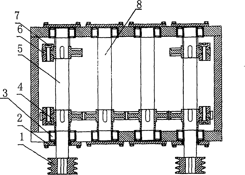
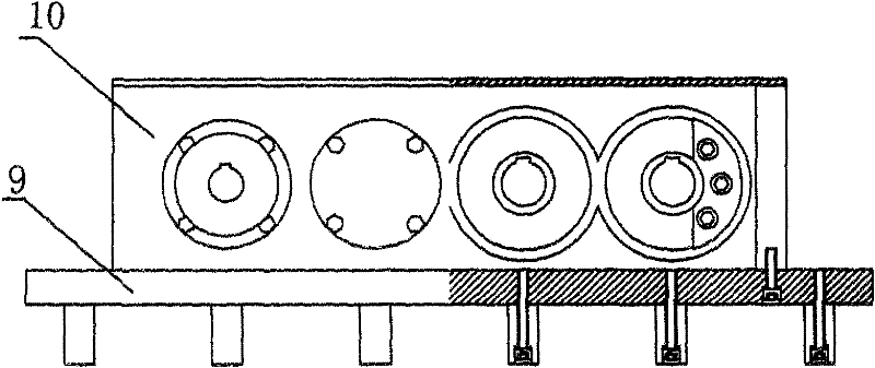
[0017] Such as figure 1 , figure 2 As shown, the vibration box of the block forming machine includes a vibration box 10 fixed on the vibration platform 9, the box 10 is equipped with two main shafts 5 and two transmission shafts 8, and one end of the two main shafts 5 passes through the box , a belt pulley 1 is provided at its end, and two transmission shafts 8 are located on the inner sides of the two main shafts 5. A synchronous gear 4 is respectively installed on the main shaft 5 and the transmission shaft 8, and is meshed with each other to realize the two main shafts The synchronous reverse rotation of the two main shafts 5 is equipped with a flange 6 respectively, and two M16 socket head cap screws are respectively fixed on the two sides of each synchronous gear 4 and flange 6. Eccentric block7. Bearings 3 are arranged at the joints between the ends of the main shaft 5 and the transmission shaft 8 and the vibration box 10 , and an oil seal 2 is provided on the outer w...


PUM


Abstract

The invention discloses a vibration box of a brick making machine, which comprises a vibration box body fixed on a vibration platform, wherein two main shafts and two transmission shafts are arranged in the box body; one end of the two main shafts passes through the box body; belt pulleys are arranged at end parts of the main shafts; the main shafts and the transmission shafts are provided with asynchromesh gear respectively, and the synchromesh gears are meshed mutually; the rear ends of the two main shafts are provided with a flange plate respectively; and eccentric blocks are fixed on thesynchromesh gears on the main shafts and end faces of both sides of the flange plates. When the vibration box operates, two main shafts of the vibration box are driven by a motor or a hydraulic motorthrough the belt pulleys to make synchronous reverse rotation, so that the vertical directional vibration of the vibration platform of the brick making machine and a casting box is realized. The vibration box has the advantages of large excentricity, small starting drag torque, quick vibration starting, short time of vibration starting and vibration stop and large exciting force.

Description

technical field [0001] The invention belongs to the technical field of block forming machines, and in particular relates to an upper vibration device of a block forming machine. Background technique [0002] The vibration device is an important part of the block forming machine, which makes the materials in the mold box compact and form through vibration. The vibrating device of the existing block forming machine includes a box body, two eccentric shafts and eccentric blocks of the same weight respectively arranged on the two eccentric shafts are housed in the box body, a synchronous gear is connected between the two eccentric shafts, The eccentric shaft, eccentric block and synchronous gear are all placed in a box fixed on the lower side of the vibrating table. One end of the two eccentric shafts passes through the box respectively. There are pulleys on the two shaft ends, and the motor drives the two shafts through the pulleys. The eccentric block on the root eccentric sh...

Claims


Application Information

Patent Timeline
Patent Type & Authority Patents(China)
IPC IPC(8): B28B1/087
Inventor 夏雷邢秀峰巩全营李守华于名霞
Owner 高成法
Learn More