Novel direct-current converter valve test unit

A technology for a DC converter valve and a display unit, which is applied in the field of power systems, can solve problems such as damage to components and equipment of the converter valve, and achieve the effect of simplifying circuit design and facilitating analysis and problem finding.

Active Publication Date: 2010-05-19
CHINA ELECTRIC POWER RES INST +2
View PDF0 Cites 40 Cited by
  • Summary
  • Abstract
  • Description
  • Claims
  • Application Information

AI Technical Summary

Problems solved by technology

Otherwise, it may cause damage to converter valve components or routine test equipment during other routine tests

Method used


Image

  • Novel direct-current converter valve test unit
  • Novel direct-current converter valve test unit
  • Novel direct-current converter valve test unit

Examples


Embodiment Construction

[0052] The present invention is realized by adopting the following technical solutions: the DC converter valve test unit mainly completes the following tests:

[0053] 1) Converter valve impedance test;

[0054] 2) GU energy storage time test;

[0055] 3) Thyristor low voltage trigger test;

[0056] 4) Thyristor reverse recovery period protection test;

[0057] 5) Endurance test after the reverse recovery period of the thyristor;

[0058] 6) Thyristor positive polarity dv / dt withstand test;

[0059] 7) Thyristor forward overvoltage and dv / dt protection test;

[0060] 8) Negative polarity dv / dt tolerance test;

[0061] 9) Low pressure trigger test after the test;

[0062] 10) Impedance test after the test.

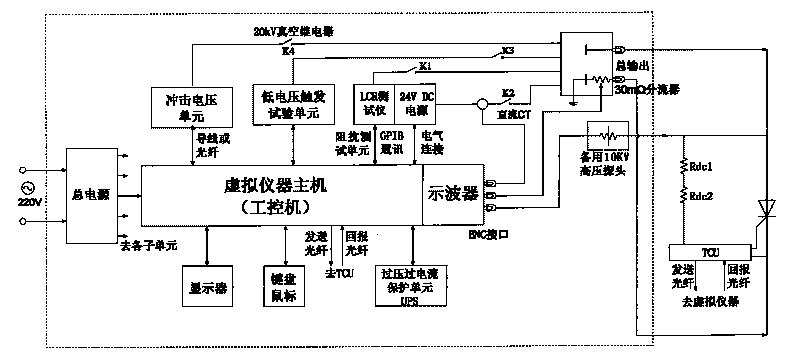
[0063] The principle block diagram of the valve test unit is attached figure 1 As shown, the DC converter valve test device includes industrial computer, impulse voltage unit, low voltage trigger test unit, impedance tester LCR, 24V power supply, valve voltage and cur...


PUM


Abstract

The invention relates to a novel direct-current converter valve test unit and a test method thereof. The test unit comprises an industrial computer, a surge voltage unit, a low-voltage triggering test unit, an impedance tester LCR, a 24V power supply, a valve voltage-current waveform acquisition system, a keyboard mouse, a display unit and an over-voltage and over-current protection unit. After a test is performed, the display unit can display each testing voltage-current waveform, and if a test is failed, the novel direct-current converter valve test unit is convenient to analyze and search problems.

Description

technical field [0001] The invention relates to the field of power systems, in particular to a novel DC converter valve test unit. Background technique [0002] The DC converter valve test unit can conduct a comprehensive inspection of the thyristor pole wiring correctness, GU (gate unit) function and thyristor, damping resistor, damping capacitor and DC voltage equalizing resistor during the routine test of the converter valve. It is also possible to complete a comprehensive test and inspection of the thyristor-level equipment of the converter valve during major and minor repairs at the converter station to ensure the safe operation of the converter valve. [0003] The traditional DC converter valve test unit has some shortcomings. It cannot display the voltage and current waveforms of the thyristors under test. When the test fails, it is not conducive to analyzing and finding the cause of the failure, and the test results are not intuitive enough. The test items are not c...

Claims


Application Information

Patent Timeline
Patent Type & Authority Applications(China)
IPC IPC(8): G01R31/00G01R31/327
Inventor 温家良王华锋魏晓光
Owner CHINA ELECTRIC POWER RES INST
Why Eureka
Try Eureka