Optimization design method of skeleton structure of airplane assembly tool

A technology for optimizing design and skeleton structure, applied in the direction of calculation, special data processing applications, instruments, etc., can solve the problems of shortening the design cycle of aircraft assembly tooling skeleton structure, high design cost, long design cycle, etc., to shorten the design cycle, weight, etc. The effect of reducing and reducing weight

Inactive Publication Date: 2010-05-19
HAIAN LIANKE AUTOMOBILE PARTS +1
View PDF0 Cites 14 Cited by
  • Summary
  • Abstract
  • Description
  • Claims
  • Application Information

AI Technical Summary

Problems solved by technology

[0006] In order to overcome the deficiencies of the prior art aircraft assembly tooling skeleton structure being bulky, long design period, and high design cost, the present invention provides an optimization design method for the aircraft assembly tooling skeleton structure, which can solve the optimization problem of discrete variables by using genetic algorithm , can realize the intelligent selection of existing profile specifications in a short time, complete the optimization design of the skeleton structure, reduce the weight of the tooling structure while meeting the rigidity requirements of the tooling, shorten the design cycle of the skeleton structure of the aircraft assembly tooling, and reduce production cost

Method used


Image

  • Optimization design method of skeleton structure of airplane assembly tool
  • Optimization design method of skeleton structure of airplane assembly tool
  • Optimization design method of skeleton structure of airplane assembly tool

Examples


Embodiment 1

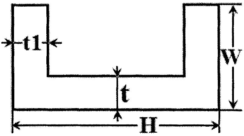
[0024] Embodiment 1: refer to figure 1 . The skeleton of the designed frame structure is welded by channel steel, and the initial design dimensions of the skeleton are: W=55mm, H=126mm, t=5.5mm. The positioning part is welded on the skeleton, and the external load is mainly transmitted to the skeleton through the positioning part. The displacement of the positioning part of the positioning part is the standard for testing whether the structural stiffness is satisfied. The tooling design requires that the comprehensive displacement of the positioning part of each positioning part is within 0.35mm.

[0025] 1) Create profile specification library.

[0026] There are about 30 specifications of commonly used channel steel, as shown in Table 1, the size data of the 30 specifications of channel steel are written into the profile specification database file in order from small to large, and the serial number of each profile size is used as its specification code. The initial struct...

Embodiment 2

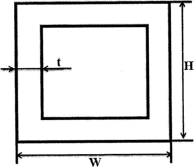
[0053] Embodiment 2: refer to figure 2 . The skeleton of the designed frame structure is welded by square steel. The initial design dimensions of each profile of the skeleton are shown in Table 7, which are: W=160mm, H=160mm, t=8mm; W=120mm, H=120mm, t=8mm . The tooling design requires that the comprehensive displacement of each stress point be within 0.3mm.

[0054] 1) Create profile specification library.

[0055] There are about 29 specifications of commonly used square steel, as shown in Table 5, the size data of the 29 specifications of square steel are written in the profile specification library file in order from small to large, and the serial number of each profile size is used as its specification code. The correspondence between the initial structural size of each profile used in the skeleton and the profile number in the profile specification library is shown in Table 7.

[0056] 2) Establish a finite element model.

[0057] Properly simplify the frame structur...


PUM


Abstract

The invention discloses an optimization design method of a skeleton structure of an airplane assembly tool, which is used for the optimization design of a skeleton structure of an airplane assembly tool. The method comprises the following steps of: building a profile specification library file; then building a finite element model of a tool skeleton in MSC.PATRAN; generating a BDF file of the finite element model in finite element software; setting an input parameter of a genetic algorithm; transferring MSC.NASTRAN to analyze the BDF file by adopting the genetic algorithm; generating a new variable sequence according to an analysis result; meanwhile, selecting a corresponding profile in the profile library by utilizing other external programs according the new variable sequence; writing the size information of the profile into the BDF file; and then repeating the steps until optimized calculation ends. Due to the adoption of the genetic algorithm, the method solves the optimization problem of discrete variables, lightens the weight of a tool structure under the condition of meeting the rigidity requirement of the tool, shortens the design period of the skeleton structure of the airplane assembly tool and reduces the production cost.

Description

technical field [0001] The invention relates to an optimal design method, in particular to an optimal design method for the frame structure of an aircraft assembly tool. Background technique [0002] Existing aircraft assembly tooling (also known as assembly jig, assembly fixture) is a process equipment suitable for aircraft structure and production characteristics used in the aircraft assembly process, usually consisting of tooling skeleton, positioning parts, clamping parts and other auxiliary equipment . The tooling skeleton is the base of the aircraft assembly tooling. It is used to fix and support positioning parts, clamping parts and other components to maintain the accuracy and stability of the spatial position of each component, so it must have sufficient rigidity. In addition, reducing the design cycle of tooling can also reduce the design and production cycle of the aircraft to a certain extent, thereby reducing the design and production cost of the aircraft. [...

Claims


Application Information

Patent Timeline
Patent Type & Authority Applications(China)
IPC IPC(8): G06F17/50G06N3/12
Inventor 张卫红王振培刘虎王丹朱继宏罗小桃
Owner HAIAN LIANKE AUTOMOBILE PARTS
Why Eureka
Try Eureka